ATEVK1104 Atmel, ATEVK1104 Datasheet - Page 388
ATEVK1104
Manufacturer Part Number
ATEVK1104
Description
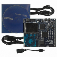
KIT DEV/EVAL FOR AVR32 AT32UC3A
Manufacturer
Atmel
Series
AVR®32r
Type
MCUr
Datasheets
1.ATAVRONE-PROBECBL.pdf
(16 pages)
2.ATEVK1104.pdf
(826 pages)
3.ATEVK1104.pdf
(90 pages)
4.ATEVK1104.pdf
(6 pages)
5.ATEVK1104.pdf
(12 pages)
Specifications of ATEVK1104
Contents
Evaluation Board, Software and Documentation
Processor To Be Evaluated
AT32UC3A3
Data Bus Width
32 bit
Interface Type
USB, SPI, USART
Silicon Manufacturer
Atmel
Core Architecture
AVR
Core Sub-architecture
AVR UC3
Silicon Core Number
AT32UC3A3256
Silicon Family Name
AVR
Kit Contents
Board CD Docs
Rohs Compliant
Yes
For Use With/related Products
AT32UC3A3
Lead Free Status / RoHS Status
Lead free / RoHS Compliant
Available stocks
Company
Part Number
Manufacturer
Quantity
Price
Company:

Part Number:
ATEVK1104
Manufacturer:
Atmel
Quantity:
135


27.6.5.4
27.6.6
27.6.6.1
32058J–AVR32–04/11
Data Float Wait States
Read to Write Wait State
READ_MODE
Due to an internal mechanism, a wait cycle is always inserted between consecutive read and
write SMC accesses.
This wait cycle is referred to as a read to write wait state in this document.
This wait cycle is applied in addition to chip select and reload user configuration wait states
when they are to be inserted. See
Some memory devices are slow to release the external bus. For such devices, it is necessary to
add wait states (data float wait states) after a read access:
• before starting a read access to a different external memory
• before starting a write access to the same device or to a different external one.
The Data Float Output Time (t
TDF_CYCLES field of the MODE register for the corresponding chip select. The value of
TDF_CYCLES indicates the number of data float wait cycles (between 0 and 15) before the
external device releases the bus, and represents the time allowed for the data output to go to
high impedance after the memory is disabled.
Data float wait states do not delay internal memory accesses. Hence, a single access to an
external memory with long t
memory.
The data float wait states management depends on the READ_MODE and the TDF_MODE
fields of the MODE register for the corresponding chip select.
Setting the READ_MODE to 1 indicates to the SMC that the NRD signal is responsible for turn-
ing off the tri-state buffers of the external memory device. The Data Float Period then begins
after the rising edge of the NRD signal and lasts TDF_CYCLES MCK cycles.
When the read operation is controlled by the NCS signal (READ_MODE = 0), the TDF field gives
the number of MCK cycles during which the data bus remains busy after the rising edge of NCS.
Figure 27-21
assuming a data float period of 2 cycles (TDF_CYCLES = 2).
ation when controlled by NCS (READ_MODE = 0) and the TDF_CYCLES parameter equals 3.
illustrates the Data Float Period in NRD-controlled mode (READ_MODE =1),
DF
will not slow down the execution of a program from internal
DF
Figure 27-17 on page
) for each external memory device is programmed in the
384.
Figure 27-22
shows the read oper-
AT32UC3A
388
Related parts for ATEVK1104
Image
Part Number
Description
Manufacturer
Datasheet
Request
R

Part Number:
Description:
DEV KIT FOR AVR/AVR32
Manufacturer:
Atmel
Datasheet:

Part Number:
Description:
INTERVAL AND WIPE/WASH WIPER CONTROL IC WITH DELAY
Manufacturer:
ATMEL Corporation
Datasheet:
Part Number:
Description:
Low-Voltage Voice-Switched IC for Hands-Free Operation
Manufacturer:
ATMEL Corporation
Datasheet:
Part Number:
Description:
MONOLITHIC INTEGRATED FEATUREPHONE CIRCUIT
Manufacturer:
ATMEL Corporation
Datasheet:
Part Number:
Description:
AM-FM Receiver IC U4255BM-M
Manufacturer:
ATMEL Corporation
Datasheet:
Part Number:
Description:
Monolithic Integrated Feature Phone Circuit
Manufacturer:
ATMEL Corporation
Datasheet:
Part Number:
Description:
Multistandard Video-IF and Quasi Parallel Sound Processing
Manufacturer:
ATMEL Corporation
Datasheet:
Part Number:
Description:
High-performance EE PLD
Manufacturer:
ATMEL Corporation
Datasheet:
Part Number:
Description:
8-bit Flash Microcontroller
Manufacturer:
ATMEL Corporation
Datasheet:
Part Number:
Description:
2-Wire Serial EEPROM
Manufacturer:
ATMEL Corporation
Datasheet: