ATEVK1104 Atmel, ATEVK1104 Datasheet - Page 677
ATEVK1104
Manufacturer Part Number
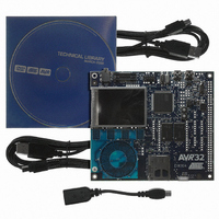
ATEVK1104
Description
KIT DEV/EVAL FOR AVR32 AT32UC3A
Manufacturer
Atmel
Series
AVR®32r
Type
MCUr
Datasheets
1.ATAVRONE-PROBECBL.pdf
(16 pages)
2.ATEVK1104.pdf
(826 pages)
3.ATEVK1104.pdf
(90 pages)
4.ATEVK1104.pdf
(6 pages)
5.ATEVK1104.pdf
(12 pages)
Specifications of ATEVK1104
Contents
Evaluation Board, Software and Documentation
Processor To Be Evaluated
AT32UC3A3
Data Bus Width
32 bit
Interface Type
USB, SPI, USART
Silicon Manufacturer
Atmel
Core Architecture
AVR
Core Sub-architecture
AVR UC3
Silicon Core Number
AT32UC3A3256
Silicon Family Name
AVR
Kit Contents
Board CD Docs
Rohs Compliant
Yes
For Use With/related Products
AT32UC3A3
Lead Free Status / RoHS Status
Lead free / RoHS Compliant
Available stocks
Company
Part Number
Manufacturer
Quantity
Price
Company:

Part Number:
ATEVK1104
Manufacturer:
Atmel
Quantity:
135


32.6.2
32.6.2.1
Figure 32-3. Functional View of the Channel Block Diagram
32.6.2.2
32058J–AVR32–04/11
PWM Channel
Block Diagram
inputs from
Waveform Properties
from clock
Peripheral
generator
inputs
Bus
Channel
The clock generator is divided in three blocks:
Each linear divider can independently divide one of the clocks of the modulo n counter. The
selection of the clock to be divided is made according to the PREA (PREB) field of the PWM
Mode register (MR). The resulting clock clkA (clkB) is the clock selected divided by DIVA (DIVB)
field value in the PWM Mode register (MR).
After a reset of the PWM controller, DIVA (DIVB) and PREA (PREB) in the PWM Mode register
are set to 0. This implies that after reset clkA (clkB) are turned off.
At reset, all clocks provided by the modulo n counter are turned off except clock “clk”. This situa-
tion is also true when the PWM master clock is turned off through the Power Management
Controller.
Each of the 7 channels is composed of three blocks:
• A clock selector which selects one of the clocks provided by the clock generator described in
• An internal counter clocked by the output of the clock selector. This internal counter is
• A comparator used to generate events according to the internal counter value. It also computes
The different properties of output waveforms are:
• the internal clock selection. The internal channel counter is clocked by one of the clocks
• the waveform period. This channel parameter is defined in the CPRD field of the CPRDx
Selector
Clock
Section 32.6.1 ”PWM Clock Generator” on page
incremented or decremented according to the channel configuration and comparators events.
The size of the internal counter is 20 bits.
the PWMx output waveform according to the configuration.
provided by the clock generator described in the previous section. This channel parameter is
defined in the CPRE field of the CMRx register. This field is reset at 0.
register.
– a modulo n counter which provides 11 clocks: F
– two linear dividers (1, 1/2, 1/3, ... 1/255) that provide two separate clocks: clkA and
F
clkB
MCK
/32, F
MCK
/64, F
Counter
Internal
MCK
/128, F
MCK
/256, F
Comparator
MCK
676.
/512, F
MCK
, F
MCK
MCK
/1024
/2, F
MCK
PWMx output waveform
/4, F
AT32UC3A
MCK
/8, F
MCK
/16,
677
Related parts for ATEVK1104
Image
Part Number
Description
Manufacturer
Datasheet
Request
R

Part Number:
Description:
DEV KIT FOR AVR/AVR32
Manufacturer:
Atmel
Datasheet:

Part Number:
Description:
INTERVAL AND WIPE/WASH WIPER CONTROL IC WITH DELAY
Manufacturer:
ATMEL Corporation
Datasheet:
Part Number:
Description:
Low-Voltage Voice-Switched IC for Hands-Free Operation
Manufacturer:
ATMEL Corporation
Datasheet:
Part Number:
Description:
MONOLITHIC INTEGRATED FEATUREPHONE CIRCUIT
Manufacturer:
ATMEL Corporation
Datasheet:
Part Number:
Description:
AM-FM Receiver IC U4255BM-M
Manufacturer:
ATMEL Corporation
Datasheet:
Part Number:
Description:
Monolithic Integrated Feature Phone Circuit
Manufacturer:
ATMEL Corporation
Datasheet:
Part Number:
Description:
Multistandard Video-IF and Quasi Parallel Sound Processing
Manufacturer:
ATMEL Corporation
Datasheet:
Part Number:
Description:
High-performance EE PLD
Manufacturer:
ATMEL Corporation
Datasheet:
Part Number:
Description:
8-bit Flash Microcontroller
Manufacturer:
ATMEL Corporation
Datasheet:
Part Number:
Description:
2-Wire Serial EEPROM
Manufacturer:
ATMEL Corporation
Datasheet: