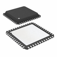
ATA6613P-PLQW Atmel, ATA6613P-PLQW Datasheet - Page 209

ATA6613P-PLQW
Manufacturer Part Number
ATA6613P-PLQW
Description
MCU W/LIN TXRX REG WTCHDG 48-QFN
Manufacturer
Atmel
Series
AVR® ATA66 LIN-SBCr
Datasheet
1.ATA6612-EK.pdf
(364 pages)
Specifications of ATA6613P-PLQW
Core Processor
AVR
Core Size
8-Bit
Speed
16MHz
Connectivity
I²C, LIN, SPI, UART/USART
Peripherals
Brown-out Detect/Reset, POR, PWM, WDT
Number Of I /o
23
Program Memory Size
16KB (16K x 8)
Program Memory Type
FLASH
Eeprom Size
512 x 8
Ram Size
1K x 8
Voltage - Supply (vcc/vdd)
2.7 V ~ 5.5 V
Data Converters
A/D 8x10b
Oscillator Type
Internal
Operating Temperature
-40°C ~ 125°C
Package / Case
48-QFN Exposed Pad
Processor Series
ATA6x
Core
AVR8
Data Bus Width
8 bit
Data Ram Size
1 KB
Interface Type
I2C, SPI, USART
Maximum Clock Frequency
16 MHz
Number Of Programmable I/os
23
Number Of Timers
3
Maximum Operating Temperature
+ 125 C
Mounting Style
SMD/SMT
Minimum Operating Temperature
- 40 C
On-chip Adc
10 bit, 8 Channel
Lead Free Status / RoHS Status
Lead free / RoHS Compliant
Available stocks
Company
Part Number
Manufacturer
Quantity
Price
Company:
Part Number:
ATA6613P-PLQW
Manufacturer:
ATMEL
Quantity:
5 000
Part Number:
ATA6613P-PLQW
Manufacturer:
ATMEL/爱特梅尔
Quantity:
20 000
- Current page: 209 of 364
- Download datasheet (7Mb)
Figure 6-74. Sampling of Data and Parity Bit
Figure 6-75. Stop Bit Sampling and Next Start Bit Sampling
9111H–AUTO–01/11
(U2X = 0)
(U2X = 1)
(U2X = 0)
(U2X = 1)
Sample
Sample
Sample
Sample
RxD
RxD
The decision of the logic level of the received bit is taken by doing a majority voting of the logic
value to the three samples in the center of the received bit. The center samples are empha-
sized on the figure by having the sample number inside boxes. The majority voting process is
done as follows: If two or all three samples have high levels, the received bit is registered to be
a logic 1. If two or all three samples have low levels, the received bit is registered to be a logic
0. This majority voting process acts as a low pass filter for the incoming signal on the RxDn
pin. The recovery process is then repeated until a complete frame is received. Including the
first stop bit. Note that the Receiver only uses the first stop bit of a frame.
Figure 6-75
bit of the next frame.
The same majority voting is done to the stop bit as done for the other bits in the frame. If the
stop bit is registered to have a logic 0 value, the Frame Error (FEn) Flag will be set.
A new high to low transition indicating the start bit of a new frame can come right after the last
of the bits used for majority voting. For Normal Speed mode, the first low level sample can be
at point marked (A) in
to (B). (C) marks a stop bit of full length. The early start bit detection influences the operational
range of the Receiver.
1
1
1
1
2
2
3
2
3
2
shows the sampling of the stop bit and the earliest possible beginning of the start
4
4
5
3
5
3
Figure
6
6
7
4
7
4
6-75. For Double Speed mode the first low level must be delayed
8
8
STOP 1
BIT n
9
5
9
5
10
10
Atmel ATA6612/ATA6613
(A)
0/1 0/1 0/1
11
6
6
12
(B)
0/1
13
7
14
15
8
16
(C)
1
1
209
Related parts for ATA6613P-PLQW
Image
Part Number
Description
Manufacturer
Datasheet
Request
R

Part Number:
Description:
MCU W/LIN TXRX REG WTCHDG 48-QFN
Manufacturer:
Atmel
Datasheet:

Part Number:
Description:
Ata6613
Manufacturer:
ATMEL Corporation
Datasheet:

Part Number:
Description:
BOARD DEMO LIN-MCM FOR ATA6613
Manufacturer:
Atmel
Datasheet:

Part Number:
Description:
DEV KIT FOR AVR/AVR32
Manufacturer:
Atmel
Datasheet:

Part Number:
Description:
INTERVAL AND WIPE/WASH WIPER CONTROL IC WITH DELAY
Manufacturer:
ATMEL Corporation
Datasheet:

Part Number:
Description:
Low-Voltage Voice-Switched IC for Hands-Free Operation
Manufacturer:
ATMEL Corporation
Datasheet:

Part Number:
Description:
MONOLITHIC INTEGRATED FEATUREPHONE CIRCUIT
Manufacturer:
ATMEL Corporation
Datasheet:

Part Number:
Description:
AM-FM Receiver IC U4255BM-M
Manufacturer:
ATMEL Corporation
Datasheet:

Part Number:
Description:
Monolithic Integrated Feature Phone Circuit
Manufacturer:
ATMEL Corporation
Datasheet:

Part Number:
Description:
Multistandard Video-IF and Quasi Parallel Sound Processing
Manufacturer:
ATMEL Corporation
Datasheet:

Part Number:
Description:
High-performance EE PLD
Manufacturer:
ATMEL Corporation
Datasheet:

Part Number:
Description:
8-bit Flash Microcontroller
Manufacturer:
ATMEL Corporation
Datasheet:


