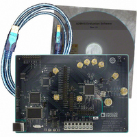
AD9910/PCBZ Analog Devices Inc, AD9910/PCBZ Datasheet - Page 4

AD9910/PCBZ
Manufacturer Part Number
AD9910/PCBZ
Description
Direct Digital Synthesis Evaluation Board
Manufacturer
Analog Devices Inc
Series
AgileRF™r
Specifications of AD9910/PCBZ
Silicon Manufacturer
Analog Devices
Application Sub Type
Direct Digital Synthesizer
Kit Application Type
Clock & Timing
Silicon Core Number
AD9910
Kit Contents
Board
Design Resources
Synchronizing Multiple AD9910 1 GSPS Direct Digital Synthesizers (CN0121)
Main Purpose
Timing, Direct Digital Synthesis (DDS)
Embedded
No
Utilized Ic / Part
AD9910
Primary Attributes
14-Bit DAC, 32-Bit Tuning Word Width
Secondary Attributes
1GHz, Graphical User Interface
Lead Free Status / RoHS Status
Lead free / RoHS Compliant
Lead Free Status / RoHS Status
Lead free / RoHS Compliant, Lead free / RoHS Compliant
Other names
Q3335404
AD9910
REVISION HISTORY
8/10—Rev. B to Rev. C
Changes to XTAL_SEL Input Parameter in Table 1 ..................... 8
Changes to Table 2 ............................................................................ 9
Changes to Transmit Enable (TxENABLE) Section .................. 21
12/08—Rev. A to Rev. B
Changes to Figure 2 .......................................................................... 5
Changes to I/O_UPDATE Pulse Width Parameter and
Minimum Profile Toggle Period Parameter in Table 1 ................ 7
Added XTAL_SEL Input Parameter in Table 1 ............................. 8
Changes to Table 3 .......................................................................... 11
Changes to Figure 20 ...................................................................... 16
Changes to Figure 22 ...................................................................... 17
Changes to Figure 23 ...................................................................... 18
Changes to Figure 24 ...................................................................... 19
Changes to Figure 25 ...................................................................... 20
Changes to REF_CLK/ REF_CLK Overview Section ................. 24
Changes to Crystal Driven REF_CLK/ REF_CLK Section ........ 25
Changes to PLL Lock Indication Section and Output Shift
Keying (OSK) Section .................................................................... 27
Changes to DRG Slope Control Section and Normal Ramp
Generation Section ......................................................................... 30
Changes to Drover Pin Section ..................................................... 32
Changes to Figure 43 ...................................................................... 35
Changes to Figure 45 and Internal Profile Control Continuous
Waveform Timing Diagram Section ............................................ 38
Changes to Figure 47 ...................................................................... 40
Changes to Figure 48 ...................................................................... 41
Deleted I/O_UPDATE Pin Section .............................................. 41
Changes to Profiles Section ........................................................... 42
Added I/O_UPDATE, SYNC_CLK, and System Clock
Relationships Section ..................................................................... 42
Added Figure 49; Renumbered Sequentially .............................. 42
Rev. C | Page 4 of 64
Changes to Synchronization of Multiple Devices Section ........ 44
Changes to DVDD (1.8V) (Pin 17, Pin 23, Pin 30, Pin 47,
Pin 57, and Pin 64) Section and AVDD (1.8V) (Pin 89 and
Pin 92) Section ................................................................................ 47
Changes to Control Interface—Serial I/O Section .................... 48
Changes to Table 17 ....................................................................... 50
Changes to Table 19 ....................................................................... 57
Changes to Table 20 and Table 21 ................................................ 58
2/08—Rev. 0 to Rev. A
Changes to Features .......................................................................... 1
Changes to REFCLK Multiplier Specification in Table 1 ............. 5
Changes to Minimum Setup Time to SYNC_CLK ....................... 6
Changes to I/O Update/Profile[2:0] Timing Characteristics ...... 6
Changes to TxENABLE/Data Setup Time (to PDCLK) and
TxENABLE/Data Hold Time (to PDCLK) .................................... 6
Changes to Miscellaneous Timing Characteristics ....................... 6
Changes to Table 3 .......................................................................... 10
Changes to Figure 9, Figure 10, Figure 11, Figure 12, Figure 13,
and Figure 14 ................................................................................... 12
Changes to Figure 30 and Table 7................................................. 24
Changes to Automatic I/O Update Section ................................. 41
Added Table 16, Renumbered Sequentially ................................ 41
Changes to Figure 49 to Figure 53 ................................................ 43
Added Power Supply Partitioning Section .................................. 46
Changes to General Serial I/O Operation Section ..................... 47
Changes to Table 17 ....................................................................... 49
Changes to Table 19 ....................................................................... 56
Changes to Table 20 ....................................................................... 57
Added Table 32 ............................................................................... 60
5/07—Revision 0: Initial Version


