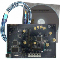
AD9910/PCBZ Analog Devices Inc, AD9910/PCBZ Datasheet - Page 2

AD9910/PCBZ
Manufacturer Part Number
AD9910/PCBZ
Description
Direct Digital Synthesis Evaluation Board
Manufacturer
Analog Devices Inc
Series
AgileRF™r
Specifications of AD9910/PCBZ
Silicon Manufacturer
Analog Devices
Application Sub Type
Direct Digital Synthesizer
Kit Application Type
Clock & Timing
Silicon Core Number
AD9910
Kit Contents
Board
Design Resources
Synchronizing Multiple AD9910 1 GSPS Direct Digital Synthesizers (CN0121)
Main Purpose
Timing, Direct Digital Synthesis (DDS)
Embedded
No
Utilized Ic / Part
AD9910
Primary Attributes
14-Bit DAC, 32-Bit Tuning Word Width
Secondary Attributes
1GHz, Graphical User Interface
Lead Free Status / RoHS Status
Lead free / RoHS Compliant
Lead Free Status / RoHS Status
Lead free / RoHS Compliant, Lead free / RoHS Compliant
Other names
Q3335404
AD9910
TABLE OF CONTENTS
Features .............................................................................................. 1
Applications ....................................................................................... 1
Functional Block Diagram .............................................................. 1
Revision History ............................................................................... 4
General Description ......................................................................... 5
Specifications ..................................................................................... 6
Absolute Maximum Ratings ............................................................ 9
Pin Configuration and Function Descriptions ........................... 10
Typical Performance Characteristics ........................................... 13
Application Circuits ....................................................................... 16
Theory of Operation ...................................................................... 17
Functional Block Detail ................................................................. 23
Electrical Specifications ............................................................... 6
Equivalent Circuits ....................................................................... 9
ESD Caution .................................................................................. 9
Single Tone Mode ....................................................................... 17
RAM Modulation Mode ............................................................ 18
Digital Ramp Modulation Mode .............................................. 19
Parallel Data Port Modulation Mode ....................................... 20
Mode Priority .............................................................................. 22
DDS Core ..................................................................................... 23
14-Bit DAC Output .................................................................... 23
Inverse Sinc Filter ....................................................................... 24
Clock Input (REF_CLK/ REF_CLK ) ........................................ 24
Parallel Data Clock (PDCLK) ............................................... 20
Transmit Enable (TxENABLE) ............................................. 21
Auxiliary DAC ........................................................................ 24
REF_CLK/ REF_CLK Overview ........................................... 24
Crystal Driven REF_CLK/ REF_CLK .................................. 25
Direct Driven REF_CLK/ REF_CLK .................................... 25
Phase-Locked Loop (PLL) Multiplier .................................. 25
PLL Charge Pump .................................................................. 26
Rev. C | Page 2 of 64
Additional Features ........................................................................ 42
PLL Lock Indication .................................................................. 27
Output Shift Keying (OSK) ....................................................... 27
Digital Ramp Generator (DRG) ............................................... 28
RAM Control .............................................................................. 33
Profiles ......................................................................................... 42
I/O_UPDATE, SYNC_CLK, and System Clock
Relationships ............................................................................... 42
Automatic I/O Update ............................................................... 43
External PLL Loop Filter Components ............................... 27
Manual OSK ............................................................................ 27
Automatic OSK ....................................................................... 28
DRG Overview ....................................................................... 28
DRG Slope Control ................................................................ 30
DRG Limit Control ................................................................ 30
DRG Accumulator Clear ....................................................... 30
Normal Ramp Generation .................................................... 30
No-Dwell Ramp Generation ................................................. 32
DROVER Pin .......................................................................... 32
RAM Overview....................................................................... 33
Load/Retrieve RAM Operation ............................................ 33
RAM Playback Operation (Waveform Generation) .......... 33
RAM_SWP_OVR (RAM Sweep Over) Pin ........................ 34
Overview of RAM Playback Modes .................................... 34
RAM Direct Switch Mode ..................................................... 34
RAM Direct Switch Mode with Zero Crossing .................. 35
RAM Ramp-Up Mode ........................................................... 35
RAM Ramp-Up Internal Profile Control Mode ................ 36
Internal Profile Control Continuous Waveform Timing
Diagram ................................................................................... 38
RAM Bidirectional Ramp Mode .......................................... 38
RAM Continuous Bidirectional Ramp Mode .................... 39
RAM Continuous Recirculate Mode ................................... 41


