MC9S12DT256MPVE Freescale Semiconductor, MC9S12DT256MPVE Datasheet - Page 643
MC9S12DT256MPVE
Manufacturer Part Number
MC9S12DT256MPVE
Description
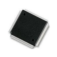
IC MCU 256K FLASH 25MHZ 112-LQFP
Manufacturer
Freescale Semiconductor
Series
HCS12r
Datasheet
1.S912XDG128F2MAL.pdf
(1348 pages)
Specifications of MC9S12DT256MPVE
Core Processor
HCS12
Core Size
16-Bit
Speed
25MHz
Connectivity
CAN, I²C, SCI, SPI
Peripherals
PWM, WDT
Number Of I /o
91
Program Memory Size
256KB (256K x 8)
Program Memory Type
FLASH
Eeprom Size
4K x 8
Ram Size
12K x 8
Voltage - Supply (vcc/vdd)
2.35 V ~ 5.25 V
Data Converters
A/D 8x10b
Oscillator Type
Internal
Operating Temperature
-40°C ~ 125°C
Package / Case
112-LQFP
Processor Series
S12D
Core
HCS12
Data Bus Width
16 bit
Data Ram Size
12 KB
Interface Type
CAN/I2C/SCI/SPI
Maximum Clock Frequency
25 MHz
Number Of Programmable I/os
91
Number Of Timers
1
Operating Supply Voltage
5 V to 2.5 V
Maximum Operating Temperature
+ 125 C
Mounting Style
SMD/SMT
3rd Party Development Tools
EWHCS12
Development Tools By Supplier
M68KIT912DP256
Minimum Operating Temperature
- 40 C
On-chip Adc
2 (8-ch x 10-bit)
No. Of I/o's
91
Eeprom Memory Size
4KB
Ram Memory Size
12KB
Cpu Speed
25MHz
No. Of Timers
1
No. Of Pwm Channels
8
Digital Ic Case Style
LQFP
Rohs Compliant
Yes
Lead Free Status / RoHS Status
Lead free / RoHS Compliant
Available stocks
Company
Part Number
Manufacturer
Quantity
Price

Company:
Part Number:
MC9S12DT256MPVE
Manufacturer:
Freescale Semiconductor
Quantity:
10 000


17.4.4.2
The arbitration scheme allows only one master to be connected to a target at any given time. The following
rules apply when prioritizing accesses from different masters to the same target bus:
17.4.5
17.4.5.1
The following interrupt requests can be triggered by the MMC module:
CPU access violation: The CPU access violation signals to the CPU detection of an error condition in the
CPU application code which is resulted in write access to the protected XGATE RAM area (see
Section 1.4.3.2, “Illegal CPU
17.5
17.5.1
CALL and RTC instructions are uninterruptable CPU instructions that automate page switching in the
program page window. The CALL instruction is similar to the JSR instruction, but the subroutine that is
called can be located anywhere in the local address space or in any Flash or ROM page visible through the
program page window. The CALL instruction calculates and stacks a return address, stacks the current
PPAGE value and writes a new instruction-supplied value to the PPAGE register. The PPAGE value
controls which of the 256 possible pages is visible through the 16 Kbyte program page window in the
64 Kbyte local CPU memory map. Execution then begins at the address of the called subroutine.
During the execution of the CALL instruction, the CPU performs the following steps:
Freescale Semiconductor
•
•
•
•
•
1. Writes the current PPAGE value into an internal temporary register and writes the new
2. Calculates the address of the next instruction after the CALL instruction (the return address) and
3. Pushes the temporarily stored PPAGE value onto the stack
4. Calculates the effective address of the subroutine, refills the queue and begins execution at the new
CPU always has priority over XGATE.
BDM access has priority over XGATE.
XGATE access to PRU registers constitutes a special case. It is always granted and stalls the CPU
and BDM for its duration.
In emulation modes all internal accesses are visible on the external bus as well.
During access to the PRU registers, the external bus is reserved.
instruction-supplied PPAGE value into the PPAGE register
pushes this 16-bit value onto the stack
address
Initialization/Application Information
Interrupts
CALL and RTC Instructions
Access Conflicts on Target Buses
Outgoing Interrupt Requests
Accesses”).
MC9S12XDP512 Data Sheet, Rev. 2.21
Chapter 17 Memory Mapping Control (S12XMMCV2)
643
Related parts for MC9S12DT256MPVE
Image
Part Number
Description
Manufacturer
Datasheet
Request
R

Part Number:
Description:
Manufacturer:
Freescale Semiconductor, Inc
Datasheet:
Part Number:
Description:
Manufacturer:
Freescale Semiconductor, Inc
Datasheet:
Part Number:
Description:
Manufacturer:
Freescale Semiconductor, Inc
Datasheet:
Part Number:
Description:
Manufacturer:
Freescale Semiconductor, Inc
Datasheet:
Part Number:
Description:
Manufacturer:
Freescale Semiconductor, Inc
Datasheet:
Part Number:
Description:
Manufacturer:
Freescale Semiconductor, Inc
Datasheet:
Part Number:
Description:
Manufacturer:
Freescale Semiconductor, Inc
Datasheet:
Part Number:
Description:
Manufacturer:
Freescale Semiconductor, Inc
Datasheet:
Part Number:
Description:
Manufacturer:
Freescale Semiconductor, Inc
Datasheet:
Part Number:
Description:
Manufacturer:
Freescale Semiconductor, Inc
Datasheet:
Part Number:
Description:
Manufacturer:
Freescale Semiconductor, Inc
Datasheet:
Part Number:
Description:
Manufacturer:
Freescale Semiconductor, Inc
Datasheet:
Part Number:
Description:
Manufacturer:
Freescale Semiconductor, Inc
Datasheet:
Part Number:
Description:
Manufacturer:
Freescale Semiconductor, Inc
Datasheet:
Part Number:
Description:
Manufacturer:
Freescale Semiconductor, Inc
Datasheet: