MC9S12DT256MPVE Freescale Semiconductor, MC9S12DT256MPVE Datasheet - Page 113
MC9S12DT256MPVE
Manufacturer Part Number
MC9S12DT256MPVE
Description
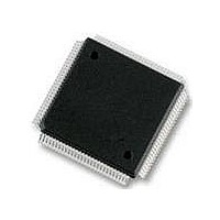
IC MCU 256K FLASH 25MHZ 112-LQFP
Manufacturer
Freescale Semiconductor
Series
HCS12r
Datasheet
1.S912XDG128F2MAL.pdf
(1348 pages)
Specifications of MC9S12DT256MPVE
Core Processor
HCS12
Core Size
16-Bit
Speed
25MHz
Connectivity
CAN, I²C, SCI, SPI
Peripherals
PWM, WDT
Number Of I /o
91
Program Memory Size
256KB (256K x 8)
Program Memory Type
FLASH
Eeprom Size
4K x 8
Ram Size
12K x 8
Voltage - Supply (vcc/vdd)
2.35 V ~ 5.25 V
Data Converters
A/D 8x10b
Oscillator Type
Internal
Operating Temperature
-40°C ~ 125°C
Package / Case
112-LQFP
Processor Series
S12D
Core
HCS12
Data Bus Width
16 bit
Data Ram Size
12 KB
Interface Type
CAN/I2C/SCI/SPI
Maximum Clock Frequency
25 MHz
Number Of Programmable I/os
91
Number Of Timers
1
Operating Supply Voltage
5 V to 2.5 V
Maximum Operating Temperature
+ 125 C
Mounting Style
SMD/SMT
3rd Party Development Tools
EWHCS12
Development Tools By Supplier
M68KIT912DP256
Minimum Operating Temperature
- 40 C
On-chip Adc
2 (8-ch x 10-bit)
No. Of I/o's
91
Eeprom Memory Size
4KB
Ram Memory Size
12KB
Cpu Speed
25MHz
No. Of Timers
1
No. Of Pwm Channels
8
Digital Ic Case Style
LQFP
Rohs Compliant
Yes
Lead Free Status / RoHS Status
Lead free / RoHS Compliant
Available stocks
Company
Part Number
Manufacturer
Quantity
Price

Company:
Part Number:
MC9S12DT256MPVE
Manufacturer:
Freescale Semiconductor
Quantity:
10 000


2.5
This section describes how to reset the CRG, and how the CRG itself controls the reset of the MCU. It
explains all special reset requirements. Since the reset generator for the MCU is part of the CRG, this
section also describes all automatic actions that occur during or as a result of individual reset conditions.
The reset values of registers and signals are provided in
Definition”. All reset sources are listed in
addresses and priorities.
2.5.1
The reset sequence is initiated by any of the following events:
Upon detection of any reset event, an internal circuit drives the RESET pin low for 128 SYSCLK cycles
(see
the internal reset circuit of the CRG cannot sequence out of current reset condition without a running
SYSCLK. The number of 128 SYSCLK cycles might be increased by n = 3 to 6 additional SYSCLK cycles
depending on the internal synchronization latency. After 128 + n SYSCLK cycles the RESET pin is
released. The reset generator of the CRG waits for additional 64 SYSCLK cycles and then samples the
RESET pin to determine the originating source.
Freescale Semiconductor
•
•
•
•
•
•
Figure
Low level is detected at the RESET pin (external reset)
Power on is detected
Low voltage is detected
Illegal Address Reset is detected (see S12XMMC Block Guide for details)
COP watchdog times out
Clock monitor failure is detected and self-clock mode was disabled (SCME=0)
Resets
2-25). Since entry into reset is asynchronous, it does not require a running SYSCLK. However,
Description of Reset Operation
COP Watchdog Reset
Illegal Address Reset
Clock Monitor Reset
Low Voltage Reset
Power on Reset
External Reset
Reset Source
MC9S12XDP512 Data Sheet, Rev. 2.21
Table 2-14. Reset Summary
Table
2-14. Refer to MCU specification for related vector
Table 2-15
Section 2.3, “Memory Map and Register
PLLCTL (CME = 1, SCME = 0)
COPCTL (CR[2:0] nonzero)
shows which vector will be fetched.
Local Enable
Chapter 2 Clocks and Reset Generator (S12CRGV6)
None
None
None
None
113
Related parts for MC9S12DT256MPVE
Image
Part Number
Description
Manufacturer
Datasheet
Request
R

Part Number:
Description:
Manufacturer:
Freescale Semiconductor, Inc
Datasheet:
Part Number:
Description:
Manufacturer:
Freescale Semiconductor, Inc
Datasheet:
Part Number:
Description:
Manufacturer:
Freescale Semiconductor, Inc
Datasheet:
Part Number:
Description:
Manufacturer:
Freescale Semiconductor, Inc
Datasheet:
Part Number:
Description:
Manufacturer:
Freescale Semiconductor, Inc
Datasheet:
Part Number:
Description:
Manufacturer:
Freescale Semiconductor, Inc
Datasheet:
Part Number:
Description:
Manufacturer:
Freescale Semiconductor, Inc
Datasheet:
Part Number:
Description:
Manufacturer:
Freescale Semiconductor, Inc
Datasheet:
Part Number:
Description:
Manufacturer:
Freescale Semiconductor, Inc
Datasheet:
Part Number:
Description:
Manufacturer:
Freescale Semiconductor, Inc
Datasheet:
Part Number:
Description:
Manufacturer:
Freescale Semiconductor, Inc
Datasheet:
Part Number:
Description:
Manufacturer:
Freescale Semiconductor, Inc
Datasheet:
Part Number:
Description:
Manufacturer:
Freescale Semiconductor, Inc
Datasheet:
Part Number:
Description:
Manufacturer:
Freescale Semiconductor, Inc
Datasheet:
Part Number:
Description:
Manufacturer:
Freescale Semiconductor, Inc
Datasheet: