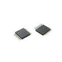
ATTINY20-XU Atmel, ATTINY20-XU Datasheet - Page 165

ATTINY20-XU
Manufacturer Part Number
ATTINY20-XU
Description
MCU AVR 2KB FLASH 12MHZ 14TSSOP
Manufacturer
Atmel
Series
AVR® ATtinyr
Datasheet
1.ATTINY20-EK1.pdf
(224 pages)
Specifications of ATTINY20-XU
Core Processor
AVR
Core Size
8-Bit
Speed
12MHz
Connectivity
I²C, SPI
Peripherals
Brown-out Detect/Reset, POR, PWM, WDT
Number Of I /o
12
Program Memory Size
2KB (1K x 16)
Program Memory Type
FLASH
Ram Size
128 x 8
Voltage - Supply (vcc/vdd)
1.8 V ~ 5.5 V
Data Converters
A/D 8x10b
Oscillator Type
Internal
Operating Temperature
-40°C ~ 85°C
Package / Case
*
Processor Series
ATtiny
Core
AVR
Data Bus Width
8 bit
Data Ram Size
128 B
Interface Type
SPI, TWI
Maximum Clock Frequency
12 MHz
Number Of Programmable I/os
12
Number Of Timers
2
Operating Supply Voltage
3.3 V
Maximum Operating Temperature
+ 85 C
Mounting Style
SMD/SMT
Minimum Operating Temperature
- 40 C
Operating Temperature Range
- 40 C to + 85 C
Lead Free Status / RoHS Status
Lead free / RoHS Compliant
Eeprom Size
-
Lead Free Status / Rohs Status
Details
Available stocks
Company
Part Number
Manufacturer
Quantity
Price
Company:
Part Number:
ATTINY20-XU
Manufacturer:
Atmel
Quantity:
904
- Current page: 165 of 224
- Download datasheet (6Mb)
19.3.2
19.3.3
8235B–AVR–04/11
Flash Memory
Configuration Section
The embedded Flash memory of ATtiny20 has four separate sections, as shown in
Table 19-3.
Notes:
ATtiny20 has one configuration byte, which resides in the configuration section. See
Table 19-4.
Table 19-5
into the configuration byte.
Table 19-5.
Notes:
Configuration bits are not affected by a chip erase but they can be cleared using the configura-
tion section erase command (see
configuration bits are locked if Non-Volatile Lock Bit 1 (NVLB1) is programmed.
Section
Code (program memory)
Configuration
Signature
Calibration
Configuration word address
0x00
0x01 ... 0x0F
Bit
7
6
5
4
3
2
1
0
1. This section is read-only.
1. See
(1)
(1)
briefly describes the functionality of all configuration bits and how they are mapped
Bit Name
–
BODLEVEL2
BODLEVEL1
BODLEVEL0
–
CKOUT
WDTON
RSTDISBL
Number of Words and Pages in the Flash
Configuration bytes
Configuration Byte 0
Table 20-6 on page 176
(1)
(1)
(1)
Size (Bytes)
Description
Reserved
Brown-out Detector trigger level
Brown-out Detector trigger level
Brown-out Detector trigger level
Reserved
System Clock Output
Watchdog Timer always on
External Reset disable
2048
16
32
16
High byte
Reserved
Reserved
“Erasing the Configuration Section” on page
for BODLEVEL Fuse decoding.
Page Size (Words)
16
16
16
16
Configuration word data
Pages
Low byte
Configuration Byte 0
Reserved
64
1
2
1
Default Value
1 (unprogrammed)
1 (unprogrammed)
1 (unprogrammed)
1 (unprogrammed)
1 (unprogrammed)
1 (unprogrammed)
1 (unprogrammed)
1 (unprogrammed)
WADDR
[4:1]
[4:1]
[4:1]
[4:1]
ATtiny20
169). Note that
Table
Table
PADDR
[10:5]
[5:5]
19-3.
–
–
19-4.
165
Related parts for ATTINY20-XU
Image
Part Number
Description
Manufacturer
Datasheet
Request
R

Part Number:
Description:
IC, MCU, 8BIT, 2K FLASH, 20SOIC
Manufacturer:
Atmel
Datasheet:

Part Number:
Description:
IC, MCU, 8BIT, 2K FLASH, 20PDIP
Manufacturer:
Atmel
Datasheet:

Part Number:
Description:
IC, MCU, 8BIT, 8K FLASH, 20PDIP
Manufacturer:
Atmel
Datasheet:

Part Number:
Description:
IC, MCU, 8BIT, 8K FLASH, 20SOIC
Manufacturer:
Atmel
Datasheet:

Part Number:
Description:
DEV KIT FOR AVR/AVR32
Manufacturer:
Atmel
Datasheet:

Part Number:
Description:
INTERVAL AND WIPE/WASH WIPER CONTROL IC WITH DELAY
Manufacturer:
ATMEL Corporation
Datasheet:

Part Number:
Description:
Low-Voltage Voice-Switched IC for Hands-Free Operation
Manufacturer:
ATMEL Corporation
Datasheet:

Part Number:
Description:
MONOLITHIC INTEGRATED FEATUREPHONE CIRCUIT
Manufacturer:
ATMEL Corporation
Datasheet:

Part Number:
Description:
AM-FM Receiver IC U4255BM-M
Manufacturer:
ATMEL Corporation
Datasheet:

Part Number:
Description:
Monolithic Integrated Feature Phone Circuit
Manufacturer:
ATMEL Corporation
Datasheet:

Part Number:
Description:
Multistandard Video-IF and Quasi Parallel Sound Processing
Manufacturer:
ATMEL Corporation
Datasheet:

Part Number:
Description:
High-performance EE PLD
Manufacturer:
ATMEL Corporation
Datasheet:


