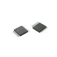
ATTINY20-XU Atmel, ATTINY20-XU Datasheet - Page 159

ATTINY20-XU
Manufacturer Part Number
ATTINY20-XU
Description
MCU AVR 2KB FLASH 12MHZ 14TSSOP
Manufacturer
Atmel
Series
AVR® ATtinyr
Datasheet
1.ATTINY20-EK1.pdf
(224 pages)
Specifications of ATTINY20-XU
Core Processor
AVR
Core Size
8-Bit
Speed
12MHz
Connectivity
I²C, SPI
Peripherals
Brown-out Detect/Reset, POR, PWM, WDT
Number Of I /o
12
Program Memory Size
2KB (1K x 16)
Program Memory Type
FLASH
Ram Size
128 x 8
Voltage - Supply (vcc/vdd)
1.8 V ~ 5.5 V
Data Converters
A/D 8x10b
Oscillator Type
Internal
Operating Temperature
-40°C ~ 85°C
Package / Case
*
Processor Series
ATtiny
Core
AVR
Data Bus Width
8 bit
Data Ram Size
128 B
Interface Type
SPI, TWI
Maximum Clock Frequency
12 MHz
Number Of Programmable I/os
12
Number Of Timers
2
Operating Supply Voltage
3.3 V
Maximum Operating Temperature
+ 85 C
Mounting Style
SMD/SMT
Minimum Operating Temperature
- 40 C
Operating Temperature Range
- 40 C to + 85 C
Lead Free Status / RoHS Status
Lead free / RoHS Compliant
Eeprom Size
-
Lead Free Status / Rohs Status
Details
Available stocks
Company
Part Number
Manufacturer
Quantity
Price
Company:
Part Number:
ATTINY20-XU
Manufacturer:
Atmel
Quantity:
904
- Current page: 159 of 224
- Download datasheet (6Mb)
18.5.3
18.5.4
18.5.5
18.5.6
18.5.7
8235B–AVR–04/11
SSTPR - Serial STore to Pointer Register
SIN - Serial IN from i/o space using direct addressing
SOUT - Serial OUT to i/o space using direct addressing
SLDCS - Serial LoaD data from Control and Status space using direct addressing
SSTCS - Serial STore data to Control and Status space using direct addressing
The SSTPR instruction stores the data byte that is shifted into the physical layer shift register to
the Pointer Register (PR). The address bit of the instruction specifies which byte of the Pointer
Register is accessed, as shown in
Table 18-4.
The SIN instruction loads data byte from the I/O space to the shift register of the physical layer
for serial read-out. The instuction uses direct addressing, the address consisting of the 6
address bits of the instruction, as shown in
Table 18-5.
The SOUT instruction stores the data byte that is shifted into the physical layer shift register to
the I/O space. The instruction uses direct addressing, the address consisting of the 6 address
bits of the instruction, as shown in
Table 18-6.
The SLDCS instruction loads data byte from the TPI Control and Status Space to the TPI physi-
cal layer shift register for serial read-out. The SLDCS instruction uses direct addressing, the
direct address consisting of the 4 address bits of the instruction, as shown in
Table 18-7.
The SSTCS instruction stores the data byte that is shifted into the TPI physical layer shift regis-
ter to the TPI Control and Status Space. The SSTCS instruction uses direct addressing, the
direct address consisting of the 4 address bits of the instruction, as shown in
Table 18-8.
Operation
PR[a]
Operation
data
Operation
I/O[a]
Operation
data
Operation
CSS[a]
←
←
←
←
←
I/O[a]
CSS[a]
data
data
data
The Serial Store to Pointer Register (SSTPR) Instruction
The Serial IN from i/o space (SIN) Instruction
The Serial OUT to i/o space (SOUT) Instruction
The Serial Load Data from Control and Status space (SLDCS) Instruction
The Serial STore data to Control and Status space (SSTCS) Instruction
Opcode
0110 100a
Opcode
0aa1 aaaa
Opcode
1aa1 aaaa
Opcode
1000 aaaa
Opcode
1100 aaaa
Table
Table
18-6.
18-4.
Table
Remarks
Bit ‘a’ addresses Pointer Register byte
Remarks
Bits marked ‘a’ form the direct, 6-bit addres
Remarks
Bits marked ‘a’ form the direct, 6-bit addres
Remarks
Bits marked ‘a’ form the direct, 4-bit addres
Remarks
Bits marked ‘a’ form the direct, 4-bit addres
18-5.
Table
Table
ATtiny20
18-7.
18-8.
159
Related parts for ATTINY20-XU
Image
Part Number
Description
Manufacturer
Datasheet
Request
R

Part Number:
Description:
IC, MCU, 8BIT, 2K FLASH, 20SOIC
Manufacturer:
Atmel
Datasheet:

Part Number:
Description:
IC, MCU, 8BIT, 2K FLASH, 20PDIP
Manufacturer:
Atmel
Datasheet:

Part Number:
Description:
IC, MCU, 8BIT, 8K FLASH, 20PDIP
Manufacturer:
Atmel
Datasheet:

Part Number:
Description:
IC, MCU, 8BIT, 8K FLASH, 20SOIC
Manufacturer:
Atmel
Datasheet:

Part Number:
Description:
DEV KIT FOR AVR/AVR32
Manufacturer:
Atmel
Datasheet:

Part Number:
Description:
INTERVAL AND WIPE/WASH WIPER CONTROL IC WITH DELAY
Manufacturer:
ATMEL Corporation
Datasheet:

Part Number:
Description:
Low-Voltage Voice-Switched IC for Hands-Free Operation
Manufacturer:
ATMEL Corporation
Datasheet:

Part Number:
Description:
MONOLITHIC INTEGRATED FEATUREPHONE CIRCUIT
Manufacturer:
ATMEL Corporation
Datasheet:

Part Number:
Description:
AM-FM Receiver IC U4255BM-M
Manufacturer:
ATMEL Corporation
Datasheet:

Part Number:
Description:
Monolithic Integrated Feature Phone Circuit
Manufacturer:
ATMEL Corporation
Datasheet:

Part Number:
Description:
Multistandard Video-IF and Quasi Parallel Sound Processing
Manufacturer:
ATMEL Corporation
Datasheet:

Part Number:
Description:
High-performance EE PLD
Manufacturer:
ATMEL Corporation
Datasheet:


