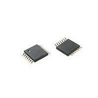
ATTINY20-XU Atmel, ATTINY20-XU Datasheet - Page 143

ATTINY20-XU
Manufacturer Part Number
ATTINY20-XU
Description
MCU AVR 2KB FLASH 12MHZ 14TSSOP
Manufacturer
Atmel
Series
AVR® ATtinyr
Datasheet
1.ATTINY20-EK1.pdf
(224 pages)
Specifications of ATTINY20-XU
Core Processor
AVR
Core Size
8-Bit
Speed
12MHz
Connectivity
I²C, SPI
Peripherals
Brown-out Detect/Reset, POR, PWM, WDT
Number Of I /o
12
Program Memory Size
2KB (1K x 16)
Program Memory Type
FLASH
Ram Size
128 x 8
Voltage - Supply (vcc/vdd)
1.8 V ~ 5.5 V
Data Converters
A/D 8x10b
Oscillator Type
Internal
Operating Temperature
-40°C ~ 85°C
Package / Case
*
Processor Series
ATtiny
Core
AVR
Data Bus Width
8 bit
Data Ram Size
128 B
Interface Type
SPI, TWI
Maximum Clock Frequency
12 MHz
Number Of Programmable I/os
12
Number Of Timers
2
Operating Supply Voltage
3.3 V
Maximum Operating Temperature
+ 85 C
Mounting Style
SMD/SMT
Minimum Operating Temperature
- 40 C
Operating Temperature Range
- 40 C to + 85 C
Lead Free Status / RoHS Status
Lead free / RoHS Compliant
Eeprom Size
-
Lead Free Status / Rohs Status
Details
Available stocks
Company
Part Number
Manufacturer
Quantity
Price
Company:
Part Number:
ATTINY20-XU
Manufacturer:
Atmel
Quantity:
904
- Current page: 143 of 224
- Download datasheet (6Mb)
17.3.8
17.3.9
8235B–AVR–04/11
Arbitration
Synchronization
In the case where the slave is stretching the clock the master will be forced into a wait-state until
the slave is ready and vice versa.
A master can only start a bus transaction if it has detected that the bus is idle. As the TWI bus is
a multi master bus, it is possible that two devices initiate a transaction at the same time. This
results in multiple masters owning the bus simultaneously. This is solved using an arbitration
scheme where the master loses control of the bus if it is not able to transmit a high level on the
SDA line. The masters who lose arbitration must then wait until the bus becomes idle (i.e. wait
for a STOP condition) before attempting to reacquire bus ownership. Slave devices are not
involved in the arbitration procedure.
Figure 17-9. TWI Arbitration
Figure 17-9
devices are able to issue a START condition, but DEVICE1 loses arbitration when attempting to
transmit a high level (bit 5) while DEVICE2 is transmitting a low level.
Arbitration between a repeated START condition and a data bit, a STOP condition and a data
bit, or a repeated START condition and STOP condition are not allowed and will require special
handling by software.
A clock synchronization algorithm is necessary for solving situations where more than one mas-
ter is trying to control the SCL line at the same time. The algorithm is based on the same
principles used for clock stretching previously described.
two masters are competing for the control over the bus clock. The SCL line is the wired-AND
result of the two masters clock outputs.
shows an example where two TWI masters are contending for bus ownership. Both
Figure 17-10
shows an example where
ATtiny20
143
Related parts for ATTINY20-XU
Image
Part Number
Description
Manufacturer
Datasheet
Request
R

Part Number:
Description:
IC, MCU, 8BIT, 2K FLASH, 20SOIC
Manufacturer:
Atmel
Datasheet:

Part Number:
Description:
IC, MCU, 8BIT, 2K FLASH, 20PDIP
Manufacturer:
Atmel
Datasheet:

Part Number:
Description:
IC, MCU, 8BIT, 8K FLASH, 20PDIP
Manufacturer:
Atmel
Datasheet:

Part Number:
Description:
IC, MCU, 8BIT, 8K FLASH, 20SOIC
Manufacturer:
Atmel
Datasheet:

Part Number:
Description:
DEV KIT FOR AVR/AVR32
Manufacturer:
Atmel
Datasheet:

Part Number:
Description:
INTERVAL AND WIPE/WASH WIPER CONTROL IC WITH DELAY
Manufacturer:
ATMEL Corporation
Datasheet:

Part Number:
Description:
Low-Voltage Voice-Switched IC for Hands-Free Operation
Manufacturer:
ATMEL Corporation
Datasheet:

Part Number:
Description:
MONOLITHIC INTEGRATED FEATUREPHONE CIRCUIT
Manufacturer:
ATMEL Corporation
Datasheet:

Part Number:
Description:
AM-FM Receiver IC U4255BM-M
Manufacturer:
ATMEL Corporation
Datasheet:

Part Number:
Description:
Monolithic Integrated Feature Phone Circuit
Manufacturer:
ATMEL Corporation
Datasheet:

Part Number:
Description:
Multistandard Video-IF and Quasi Parallel Sound Processing
Manufacturer:
ATMEL Corporation
Datasheet:

Part Number:
Description:
High-performance EE PLD
Manufacturer:
ATMEL Corporation
Datasheet:


