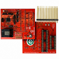
AC162078 Microchip Technology, AC162078 Datasheet - Page 313

AC162078
Manufacturer Part Number
AC162078
Description
HEADER INTRFC MPLAB ICD2 18F1330
Manufacturer
Microchip Technology
Datasheet
1.AC162078.pdf
(318 pages)
Specifications of AC162078
Accessory Type
Transition Header
Lead Free Status / RoHS Status
Not applicable / Not applicable
For Use With/related Products
ICD2
Lead Free Status / RoHS Status
Lead free / RoHS Compliant, Not applicable / Not applicable
Available stocks
Company
Part Number
Manufacturer
Quantity
Price
Company:
Part Number:
AC162078
Manufacturer:
MICROCHIP
Quantity:
12 000
- Current page: 313 of 318
- Download datasheet (3Mb)
Timer1 .............................................................................. 111
Timing Diagrams
2009 Microchip Technology Inc.
16-Bit Read/Write Mode ........................................... 114
Associated Registers ............................................... 115
Interrupt .................................................................... 114
Operation ................................................................. 112
Oscillator .......................................................... 111, 113
Oscillator Layout Considerations ............................. 113
Overflow Interrupt .................................................... 111
TMR1H Register ...................................................... 111
TMR1L Register ....................................................... 111
Use as a Clock Source ............................................ 113
Use as a Real-Time Clock ....................................... 114
A/D Conversion ........................................................ 293
Asynchronous Reception ......................................... 161
Asynchronous Transmission .................................... 158
Asynchronous Transmission (Back-to-Back) ........... 158
Automatic Baud Rate Calculation ............................ 156
Auto-Wake-up Bit (WUE) During Normal Operation 162
Auto-Wake-up Bit (WUE) During Sleep ................... 162
BRG Overflow Sequence ......................................... 156
Brown-out Reset (BOR) ........................................... 289
CLKO and I/O .......................................................... 288
Clock/Instruction Cycle .............................................. 55
Dead-Time Insertion for Complementary PWM ....... 135
Duty Cycle Update Times in Continuous Up/Down Count
Duty Cycle Update Times in Continuous Up/Down Count
Edge-Aligned PWM .................................................. 132
EUSART Synchronous Receive (Master/Slave) ...... 291
EUSART Synchronous Transmission (Master/Slave) ....
External Clock (All Modes Except PLL) ................... 286
Fail-Safe Clock Monitor ............................................ 206
Low-Voltage Detect Characteristics ......................... 283
Low-Voltage Detect Operation ................................. 189
Override Bits in Complementary Mode .................... 139
PWM Output Override Example #1 .......................... 141
PWM Output Override Example #2 .......................... 141
PWM Period Buffer Updates in Continuous Up/Down
PWM Period Buffer Updates in Free-Running Mode 130
PWM Time Base Interrupt (Free-Running Mode) .... 126
PWM Time Base Interrupt (Single-Shot Mode) ........ 127
PWM Time Base Interrupts (Continuous Up/Down Count
PWM Time Base Interrupts (Continuous Up/Down Count
Reset, Watchdog Timer (WDT), Oscillator Start-up Timer
Send Break Character Sequence ............................ 163
Slow Rise Time (MCLR Tied to V
Start of Center-Aligned PWM ................................... 133
Synchronous Reception (Master Mode, SREN) ...... 166
Synchronous Transmission ...................................... 164
Synchronous Transmission (Through TXEN) .......... 165
Time-out Sequence on POR w/PLL Enabled (MCLR Tied
Time-out Sequence on Power-up (MCLR Not Tied to
Time-out Sequence on Power-up (MCLR Not Tied to
Time-out Sequence on Power-up (MCLR Tied to V
Mode ................................................................ 132
Mode with Double Updates .............................. 133
291
Count Modes ................................................... 130
Mode with Double Updates) ............................ 128
Mode) ............................................................... 127
(OST), Power-up Timer (PWRT) ...................... 289
to V
V
V
............................................................................ 45
DD
DD
DD
, Case 1) ...................................................... 44
, Case 2) ...................................................... 44
) ............................................................... 45
DD
, V
DD
Rise > T
PWRT
DD
)
,
Timing Diagrams and Specifications ............................... 286
Top-of-Stack Access .......................................................... 52
TSTFSZ ........................................................................... 255
Two-Speed Start-up ................................................. 191, 204
Two-Word Instructions
TXSTA Register
V
Voltage Reference Specifications .................................... 282
W
Watchdog Timer (WDT) ........................................... 191, 202
WWW Address ................................................................ 314
WWW, On-Line Support ...................................................... 7
X
XORLW ........................................................................... 255
XORWF ........................................................................... 256
Timer0 and Timer1 External Clock .......................... 290
Transition for Entry to Idle Mode ............................... 36
Transition for Entry to SEC_RUN Mode .................... 33
Transition for Entry to Sleep Mode ............................ 35
Transition for Two-Speed Start-up (INTOSC to HSPLL)
Transition for Wake From Idle to Run Mode .............. 36
Transition for Wake From Sleep (HSPLL) ................. 35
Transition from RC_RUN Mode to PRI_RUN Mode .. 34
Transition from SEC_RUN Mode to PRI_RUN Mode
Transition to RC_RUN Mode ..................................... 34
CLKO and I/O Requirements ................................... 288
EUSART Synchronous Receive Requirements ....... 291
EUSART Synchronous Transmission Requirements ....
External Clock Requirements .................................. 286
PLL Clock ................................................................ 287
Reset, Watchdog Timer, Oscillator Start-up Timer, Pow-
Timer0 and Timer1 External Clock Requirements ... 290
Example Cases ......................................................... 56
BRGH Bit ................................................................. 151
Associated Registers ............................................... 203
Control Register ....................................................... 202
During Oscillator Failure .......................................... 205
Programming Considerations .................................. 202
V
204
(HSPLL) ............................................................. 33
291
er-up Timer and Brown-out Reset Requirements ..
289
PIC18F1230/1330
DD
Rise < T
PWRT
) ............................................ 44
DS39758D-page 313
Related parts for AC162078
Image
Part Number
Description
Manufacturer
Datasheet
Request
R

Part Number:
Description:
Manufacturer:
Microchip Technology Inc.
Datasheet:

Part Number:
Description:
Manufacturer:
Microchip Technology Inc.
Datasheet:

Part Number:
Description:
Manufacturer:
Microchip Technology Inc.
Datasheet:

Part Number:
Description:
Manufacturer:
Microchip Technology Inc.
Datasheet:

Part Number:
Description:
Manufacturer:
Microchip Technology Inc.
Datasheet:

Part Number:
Description:
Manufacturer:
Microchip Technology Inc.
Datasheet:

Part Number:
Description:
Manufacturer:
Microchip Technology Inc.
Datasheet:

Part Number:
Description:
Manufacturer:
Microchip Technology Inc.
Datasheet:


