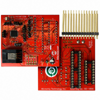
AC162078 Microchip Technology, AC162078 Datasheet - Page 144

AC162078
Manufacturer Part Number
AC162078
Description
HEADER INTRFC MPLAB ICD2 18F1330
Manufacturer
Microchip Technology
Datasheet
1.AC162078.pdf
(318 pages)
Specifications of AC162078
Accessory Type
Transition Header
Lead Free Status / RoHS Status
Not applicable / Not applicable
For Use With/related Products
ICD2
Lead Free Status / RoHS Status
Lead free / RoHS Compliant, Not applicable / Not applicable
Available stocks
Company
Part Number
Manufacturer
Quantity
Price
Company:
Part Number:
AC162078
Manufacturer:
MICROCHIP
Quantity:
12 000
- Current page: 144 of 318
- Download datasheet (3Mb)
PIC18F1230/1330
14.13 PWM Update Lockout
For a complex PWM application, the user may need to
write up to four Duty Cycle registers and the PWM Time
Base Period Register, PTPER, at a given time. In some
applications, it is important that all buffer registers be
written before the new duty cycle and period values are
loaded for use by the module.
A PWM update lockout feature may optionally be
enabled so the user may specify when new duty cycle
buffer values are valid. The PWM update lockout
feature is enabled by setting the control bit, UDIS, in
the PWMCON1 register. This bit affects all Duty Cycle
Buffer registers and the PWM Time Base Period
register, PTPER.
To perform a PWM update lockout:
1.
2.
3.
4.
14.14 PWM Special Event Trigger
The PWM module has a Special Event Trigger
capability
synchronized to the PWM time base. The A/D sampling
and conversion time may be programmed to occur at
any point within the PWM period. The Special Event
Trigger allows the user to minimize the delay between
the time when A/D conversion results are acquired and
the time when the duty cycle value is updated.
The PWM 16-bit Special Event Trigger register,
SEVTCMP (high and low), and five control bits in the
PWMCON1 register are used to control its operation.
DS39758D-page 144
Set the UDIS bit.
Write all Duty Cycle registers and PTPER, if
applicable.
Clear the UDIS bit to re-enable updates.
With this, when UDIS bit is cleared, the buffer
values will be loaded to the actual registers. This
makes a synchronous loading of the registers.
that
allows
A/D
conversions
to
be
The PTMR value for which a Special Event Trigger
should occur is loaded into the SEVTCMP register pair.
SEVTDIR bit in PWMCON1 register specifies the
counting phase when the PWM time base is in a
Continuous Up/Down Count mode.
If the SEVTDIR bit is cleared, the Special Event Trigger
will occur on the upward counting cycle of the PWM
time base. If SEVTDIR is set, the Special Event Trigger
will occur on the downward count cycle of the PWM
time base. The SEVTDIR bit only effects this operation
when the PWM timer is in the Continuous Up/Down
Count mode.
14.14.1
The PWM module will always produce Special Event
Trigger pulses. This signal may optionally be used by
the A/D module. Refer to Chapter 16.0 "10-Bit
Analog-to-Digital Converter (A/D) Module" for
details.
14.14.2
The PWM Special Event Trigger has a postscaler that
allows a 1:1 to 1:16 postscale ratio. The postscaler is
configured by writing the SEVOPS3:SEVOPS0 control
bits in the PWMCON1 register.
The Special Event Trigger output postscaler is cleared
on any write to the SEVTCMP register pair, or on any
device Reset.
Note:
The Special Event Trigger will take place
only for non-zero values in the SEVTCMP
registers.
SPECIAL EVENT TRIGGER ENABLE
SPECIAL EVENT TRIGGER
POSTSCALER
2009 Microchip Technology Inc.
Related parts for AC162078
Image
Part Number
Description
Manufacturer
Datasheet
Request
R

Part Number:
Description:
Manufacturer:
Microchip Technology Inc.
Datasheet:

Part Number:
Description:
Manufacturer:
Microchip Technology Inc.
Datasheet:

Part Number:
Description:
Manufacturer:
Microchip Technology Inc.
Datasheet:

Part Number:
Description:
Manufacturer:
Microchip Technology Inc.
Datasheet:

Part Number:
Description:
Manufacturer:
Microchip Technology Inc.
Datasheet:

Part Number:
Description:
Manufacturer:
Microchip Technology Inc.
Datasheet:

Part Number:
Description:
Manufacturer:
Microchip Technology Inc.
Datasheet:

Part Number:
Description:
Manufacturer:
Microchip Technology Inc.
Datasheet:


