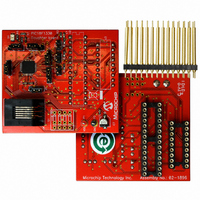
AC162078 Microchip Technology, AC162078 Datasheet - Page 125

AC162078
Manufacturer Part Number
AC162078
Description
HEADER INTRFC MPLAB ICD2 18F1330
Manufacturer
Microchip Technology
Datasheet
1.AC162078.pdf
(318 pages)
Specifications of AC162078
Accessory Type
Transition Header
Lead Free Status / RoHS Status
Not applicable / Not applicable
For Use With/related Products
ICD2
Lead Free Status / RoHS Status
Lead free / RoHS Compliant, Not applicable / Not applicable
Available stocks
Company
Part Number
Manufacturer
Quantity
Price
Company:
Part Number:
AC162078
Manufacturer:
MICROCHIP
Quantity:
12 000
- Current page: 125 of 318
- Download datasheet (3Mb)
14.3.1
In the Free-Running mode, the PWM time base
(PTMRL and PTMRH) will begin counting upwards until
the value in the PWM Time Base Period register,
PTPER (PTPERL and PTPERH), is matched. The
PTMR registers will be reset on the following input
clock edge and the time base will continue counting
upwards as long as the PTEN bit remains set.
14.3.2
In the Single-Shot mode, the PWM time base will begin
counting upwards when the PTEN bit is set. When the
value in the PTMR register matches the PTPER
register, the PTMR register will be reset on the
following input clock edge and the PTEN bit will be
cleared by the hardware to halt the time base.
14.3.3
In Continuous Up/Down Count modes, the PWM time
base counts upwards until the value in the PTPER
register matches the PTMR register. On the following
input clock edge, the timer counts downwards. The
PTDIR bit in the PTCON1 register is read-only and
indicates the counting direction. The PTDIR bit is set
when the timer counts downwards.
14.3.4
The input clock to PTMR (F
options of 1:1, 1:4, 1:16 or 1:64. These are selected by
control bits, PTCKPS<1:0>, in the PTCON0 register.
The prescaler counter is cleared when any of the
following occurs:
• Write to the PTMR register
• Write to the PTCON (PTCON0 or PTCON1) register
• Any device Reset
2009 Microchip Technology Inc.
Note:
Note:
SINGLE-SHOT MODE
PWM TIME BASE PRESCALER
FREE-RUNNING MODE
CONTINUOUS UP/DOWN COUNT
MODES
Since the PWM compare outputs are
driven to the active state when the PWM
time-base is counting downwards and
matches the duty cycle value, the PWM
outputs are held inactive during the first
half of the first period of the Continuous
Up/Down Count mode until the PTMR
begins to count down from the PTPER
value.
The PTMR register is not cleared when
PTCONx is written.
OSC
/4) has prescaler
Table 14-1 shows the minimum PWM frequencies that
can be generated with the PWM time base and the
prescaler.
(F
the table. The PWM module must be capable of
generating PWM signals at the line frequency (50 Hz or
60 Hz) for certain power control applications.
TABLE 14-1:
14.3.5
The match output of PTMR can optionally be
postscaled through a 4-bit postscaler (which gives a
1:1 to 1:16 scaling inclusive) to generate an interrupt.
The postscaler counter is cleared when any of the
following occurs:
• Write to the PTMR register
• Write to the PTCONx register
• Any device Reset
The PTMR register is not cleared when PTCONx is
written.
14.4
The PWM timer can generate interrupts based on the
modes of operation selected by the PTMOD<1:0> bits
and the postscaler bits (PTOPS<3:0>).
14.4.1
When the PWM time base is in the Free-Running mode
(PTMOD<1:0> = 00), an interrupt event is generated
each time a match with the PTPER register occurs. The
PTMR register is reset to zero in the following clock
edge.
Using a postscaler selection other than 1:1 will reduce
the frequency of interrupt events.
Minimum PWM Frequencies vs. Prescaler Value
CYC
Prescale
= 10 MHz) and PTPER = 0xFFF are assumed in
1:16
1:64
for F
1:1
1:4
PWM Time Base Interrupts
PIC18F1230/1330
PWM TIME BASE POSTSCALER
INTERRUPTS IN FREE-RUNNING
MODE
An
CYC
= 10 MIPS (PTPER = 0FFFh)
operating
MINIMUM PWM FREQUENCY
Edge-Aligned
Frequency
2441 Hz
610 Hz
153 Hz
38 Hz
PWM
frequency
DS39758D-page 125
Center-Aligned
Frequency
1221 Hz
305 Hz
of
76 Hz
19 Hz
PWM
40 MHz
Related parts for AC162078
Image
Part Number
Description
Manufacturer
Datasheet
Request
R

Part Number:
Description:
Manufacturer:
Microchip Technology Inc.
Datasheet:

Part Number:
Description:
Manufacturer:
Microchip Technology Inc.
Datasheet:

Part Number:
Description:
Manufacturer:
Microchip Technology Inc.
Datasheet:

Part Number:
Description:
Manufacturer:
Microchip Technology Inc.
Datasheet:

Part Number:
Description:
Manufacturer:
Microchip Technology Inc.
Datasheet:

Part Number:
Description:
Manufacturer:
Microchip Technology Inc.
Datasheet:

Part Number:
Description:
Manufacturer:
Microchip Technology Inc.
Datasheet:

Part Number:
Description:
Manufacturer:
Microchip Technology Inc.
Datasheet:


