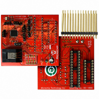
AC162078 Microchip Technology, AC162078 Datasheet - Page 308

AC162078
Manufacturer Part Number
AC162078
Description
HEADER INTRFC MPLAB ICD2 18F1330
Manufacturer
Microchip Technology
Datasheet
1.AC162078.pdf
(318 pages)
Specifications of AC162078
Accessory Type
Transition Header
Lead Free Status / RoHS Status
Not applicable / Not applicable
For Use With/related Products
ICD2
Lead Free Status / RoHS Status
Lead free / RoHS Compliant, Not applicable / Not applicable
Available stocks
Company
Part Number
Manufacturer
Quantity
Price
Company:
Part Number:
AC162078
Manufacturer:
MICROCHIP
Quantity:
12 000
PIC18F1230/1330
Code Protection ....................................................... 191, 207
COMF ............................................................................... 232
Comparator ...................................................................... 179
Comparator Specifications ............................................... 282
Comparator Voltage Reference ....................................... 183
Computed GOTO ............................................................... 54
Configuration Bits ............................................................. 191
Context Saving During Interrupts ..................................... 105
Conversion Considerations .............................................. 305
CPFSEQ .......................................................................... 232
CPFSGT ........................................................................... 233
CPFSLT ........................................................................... 233
Crystal Oscillator/Ceramic Resonator ................................ 21
Customer Change Notification Service ............................ 314
Customer Notification Service .......................................... 314
Customer Support ............................................................ 314
D
Data Addressing Modes ..................................................... 65
Data EEPROM Memory ..................................................... 81
DS39758D-page 308
How to Clear RAM (Bank 0) Using Indirect Addressing .
Implementing a Real-Time Clock Using a Timer1 Inter-
Initializing PORTA ...................................................... 87
Initializing PORTB ...................................................... 90
Reading a Flash Program Memory Word .................. 75
Saving STATUS, WREG and BSR Registers in RAM ...
Writing to Flash Program Memory ....................... 78–79
Associated Registers ............................................... 207
Configuration Register Protection ............................ 210
Data EEPROM ......................................................... 210
Program Memory ..................................................... 208
Analog Input Connection Considerations ................. 181
Associated Registers ............................................... 182
Configuration ............................................................ 180
Effects of a Reset ..................................................... 181
Interrupts .................................................................. 180
Operation ................................................................. 180
Operation During Sleep ........................................... 181
Outputs .................................................................... 180
Reference ................................................................ 180
Response Time ........................................................ 180
Accuracy and Error .................................................. 185
Associated Registers ............................................... 185
Configuring ............................................................... 183
Effects of a Reset ..................................................... 185
Operation During Sleep ........................................... 185
Comparing Options with the Extended Instruction Set
Direct .......................................................................... 65
Indexed Literal Offset ................................................. 67
Indirect ....................................................................... 65
Inherent and Literal .................................................... 65
Associated Registers ................................................. 84
EEADR Register ........................................................ 81
EECON1 and EECON2 Registers ............................. 81
Operation During Code-Protect ................................. 84
Protection Against Spurious Write ............................. 83
Reading ...................................................................... 83
Using .......................................................................... 84
Write Verify ................................................................ 83
Writing ........................................................................ 83
65
rupt Service ...................................................... 115
105
Enabled .............................................................. 68
Instructions Affected .......................................... 67
Data Memory ..................................................................... 57
DAW ................................................................................ 234
DC Characteristics ........................................................... 279
DCFSNZ .......................................................................... 235
DECF ............................................................................... 234
DECFSZ .......................................................................... 235
Development Support ...................................................... 211
Device Differences ........................................................... 304
Device Overview .................................................................. 9
Device Reset Timers ......................................................... 43
Direct Addressing .............................................................. 66
E
Effect on Standard PIC MCU Instructions ....................... 262
Effects of Power-Managed Modes on Various Clock Sources
Electrical Characteristics ................................................. 265
Enhanced Universal Synchronous Asynchronous Receiver
Equations
Errata ................................................................................... 7
EUSART
Access Bank .............................................................. 59
and the Extended Instruction Set .............................. 67
Bank Select Register (BSR) ...................................... 57
General Purpose Registers ....................................... 59
Map for PIC18F1230/1330 ........................................ 58
Special Function Registers ........................................ 60
Power-Down and Supply Current ............................ 269
Supply Voltage ........................................................ 268
Details on Individual Family Members ....................... 10
Features (table) ......................................................... 11
New Core Features ...................................................... 9
Other Special Features .............................................. 10
Oscillator Start-up Timer (OST) ................................. 43
PLL Lock Time-out ..................................................... 43
Power-up Timer (PWRT) ........................................... 43
Time-out Sequence ................................................... 43
29
Transmitter (EUSART). See EUSART.
A/D Acquisition Time ............................................... 174
A/D Minimum Charging Time ................................... 174
Calculating the Minimum Required Acquisition Time ....
PWM Frequency ...................................................... 129
PWM Period for Continuous Up/Down Count Mode 129
PWM Period for Free-Running Mode ...................... 129
PWM Resolution ...................................................... 129
Asynchronous Mode ................................................ 157
Baud Rate Generator
Baud Rate Generator (BRG) ................................... 151
Synchronous Master Mode ...................................... 164
174
12-Bit Break Character Sequence ................... 163
Associated Registers, Receive ........................ 161
Associated Registers, Transmit ....................... 159
Auto-Wake-up on Sync Break Character ........ 161
Receiver .......................................................... 160
Receiving a Break Character ........................... 163
Setting Up 9-Bit Mode with Address Detect .... 160
Transmitter ...................................................... 157
Operation in Power-Managed Modes .............. 151
Associated Registers ....................................... 152
Auto-Baud Rate Detect .................................... 155
Baud Rate Error, Calculating ........................... 152
Baud Rates, Asynchronous Modes ................. 153
High Baud Rate Select (BRGH Bit) ................. 151
Sampling .......................................................... 151
Associated Registers, Receive ........................ 166
2009 Microchip Technology Inc.


