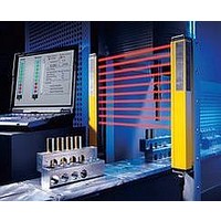
F39-EU1E Omron, F39-EU1E Datasheet - Page 842

F39-EU1E
Manufacturer Part Number
F39-EU1E
Description
F3S-B OPTIONAL PROGRAMMING KIT
Manufacturer
Omron
Datasheet
1.F39-EU1E.pdf
(865 pages)
Specifications of F39-EU1E
Leaded Process Compatible
No
Peak Reflow Compatible (260 C)
No
Light Curtain Type
Safety
Lead Free Status / RoHS Status
Contains lead / RoHS non-compliant
Lead Free Status / RoHS Status
Contains lead / RoHS non-compliant
- Current page: 842 of 865
- Download datasheet (35Mb)
Courtesy of Steven Engineering, Inc.-230 Ryan Way, South San Francisco, CA 94080-6370-Main Office: (650) 588-9200-Outside Local Area: (800) 258-9200-www.stevenengineering.com
Connection Circuit Examples
Examples of Safety Circuits
Example When Using the MS/MSF4800 Individually (Category 4)
MS/MSF4800 Settings
• Use Start/Restart Interlock Mode. (Use the PDM to set the operation mode to Start/Restart Interlock Mode.)
• Use the external relay monitor function. (Use the PDM to turn ON the EDM function.)
• Use the test input. (Use the PDM to enable the test input.)
External test switch (S1)
KM1, KM2 NO contacts
KM1, KM2 NC contacts
Start input switch (S2)
Transmitter
E1
Light interrupted
Control output
*5
Light incident
PLC input *
24 VDC
http://www.ia.omron.com/
Ground
PLC output
* The output operation mode of the auxiliary output
0 V
is the Dark-ON output mode.
*4
*3
KM2
KM1
*2
PLC
IN
Receiver
KM1
S1: External test switch
S2: Start input
KM1, KM2: Magnetic contactors
KM3: Solid-state contactor (G3J)
M: 3-phase motor
E1: 24-VDC power supply
PLC: Programmable Controller
(Used for monitoring. This is not a part of a safety system.)
*1. Make sure that both external devices have been suitably suppressed.
*2. For the MS/MS4800B, use an NC contacts for the start input switch.
*3. With the default setting, the external relay monitor input (EDM) is set
*4. Fuse (provided by the customer).
*5. The test input is disabled with the default setting. To use the test
OUT
*1
For the MS/MS4800A, refer to Start Input Methods (MS/MSF4800A
Only) on page 19. When using Auto Start Mode, use the PDM to
check that the operation mode is set to Auto Start Mode (default), and
connect the start input to 0 V.
so that the EDM is enabled and disabled with the start input. This will
prevent accessing the normal functionality of the start input.
To use both the start input and the EDM as shown in the example
safety circuits on this page, connect the PDM to the Receiver and use
the PDM to enable the EDM. If the EDM is not necessary, use the
PDM to disable the EDM, and then connect the EDM (red wire) to 0 V.
For details, refer to Mini Safe 4800 Series Light Curtains Installation
and Operating Manual.
input, connect the PDM to the Receiver and enable the test input, and
use NC contacts for the test input.
KM2
(c)Copyright OMRON Corporation 2008 All Rights Reserved.
*1
M
KM1
KM2
KM3
MS4800
12
Related parts for F39-EU1E
Image
Part Number
Description
Manufacturer
Datasheet
Request
R

Part Number:
Description:
Pair Of Flat Mounting Brackets (transmitter & Receiver)
Manufacturer:
Omron

Part Number:
Description:
Pair Of Protective Shrouds (transmitter & Receiver)
Manufacturer:
Omron

Part Number:
Description:
G6S-2GLow Signal Relay
Manufacturer:
Omron Corporation
Datasheet:

Part Number:
Description:
Compact, Low-cost, SSR Switching 5 to 20 A
Manufacturer:
Omron Corporation
Datasheet:

Part Number:
Description:
Manufacturer:
Omron Corporation
Datasheet:


