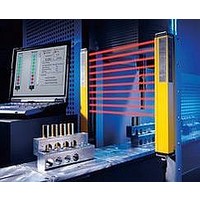
F39-EU1E Omron, F39-EU1E Datasheet - Page 818

F39-EU1E
Manufacturer Part Number
F39-EU1E
Description
F3S-B OPTIONAL PROGRAMMING KIT
Manufacturer
Omron
Datasheet
1.F39-EU1E.pdf
(865 pages)
Specifications of F39-EU1E
Leaded Process Compatible
No
Peak Reflow Compatible (260 C)
No
Light Curtain Type
Safety
Lead Free Status / RoHS Status
Contains lead / RoHS non-compliant
Lead Free Status / RoHS Status
Contains lead / RoHS non-compliant
- Current page: 818 of 865
- Download datasheet (35Mb)
Courtesy of Steven Engineering, Inc.-230 Ryan Way, South San Francisco, CA 94080-6370-Main Office: (650) 588-9200-Outside Local Area: (800) 258-9200-www.stevenengineering.com
Specifications
*1. ESPE (Electro-Sensitive Protective Equipment)
*2. AOPD (Active Opto-electronic Protective Devices)
Connections
Wire the F3SS only after all power has been turned off.
Emitter
Note: Ground the projector and receiver to the ground terminal inside the case.
Item
Sensing method
Case material
Connection method
Power supply voltage 24 VDC 10% (ripple p-p: 5% max.)
Effective aperture
angle
Current consumption
Sensing distance
Detection capability
Response time
Control outputs
Operating mode
Startup waiting time
Ambient temperature Operating/Storage: 0 to 55 C (with no icing or condensation)
Ambient humidity
Vibration resistance
Shock resistance
Degree of protection
Light source (emitted
wavelength)
Indicators
Protective circuits
Weight (packed state) Approx. 2.5 kg (1 set)
Applicable standards IEC (EN) 61496-1 TYPE4 ESPE *1, IEC(prEN)61496-2 TYPE4 AOPD *2
Accessories
J3
Terminal
number
block
+24 VDC
RTN
Terminal
name
Model
http://www.ia.omron.com/
+24 VDC
0V (GND)
Through-beam models
Aluminum (case and cap)
Connected to the terminal block on the internal board.
Emitter: 170 mA max.
Receiver: 800 mA max.
0.3 to 60 m
Opaque objects, 31 mm in diameter or greater
35 ms max.
Two PNP transistor outputs, load current 250 mA or less (residual voltage 1 V or less) (excluding voltage drop due to
cable extension), Dark ON
Auto start mode, start interlock mode, and start/restart interlock mode can all be selected using a switch in the receiver.
4 s or less
Operating/Storage: 35% to 95% (with no condensation)
Malfunction/destruction: 10 to 50 Hz, amplitude 0.7 mm, 20 sweeps each in X, Y, and Z directions
Malfunction/destruction: 100 m/s
IEC60529 Standard IP65
Infrared LED (880 nm)
Emitter: Power indicator (orange), error mode indicator (red)
Receiver: Light intensity level indicator (orange), OFF-state indicator (red), ON-state indicator (green), interlock indicator
(yellow)
Output load short and power supply reverse connection protection
Set of mounting clamps, operation manual, caps for conduits
Functions
2.5 at 3 m
Terminal block
assignments
RTN + 24VDC
2
, 1,000 times each in X, Y, and Z directions
Receiver
Terminal
J5
number
F3SS-AT60P
block
(c)Copyright OMRON Corporation 2007 All Rights Reserved.
Terminal
1
2
3
4
5
6
7
name
Control output 1
(+)
For control
output 1/2 COM (-)
Control output 2
(+)
START(-)
START(+)
+24 VDC
0V (GND)
Functions
1
Terminal block
assignments
2
3
4
5
F3SS
6
7
2
Related parts for F39-EU1E
Image
Part Number
Description
Manufacturer
Datasheet
Request
R

Part Number:
Description:
Pair Of Flat Mounting Brackets (transmitter & Receiver)
Manufacturer:
Omron

Part Number:
Description:
Pair Of Protective Shrouds (transmitter & Receiver)
Manufacturer:
Omron

Part Number:
Description:
G6S-2GLow Signal Relay
Manufacturer:
Omron Corporation
Datasheet:

Part Number:
Description:
Compact, Low-cost, SSR Switching 5 to 20 A
Manufacturer:
Omron Corporation
Datasheet:

Part Number:
Description:
Manufacturer:
Omron Corporation
Datasheet:


