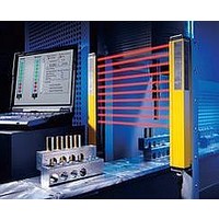
F39-EU1E Omron, F39-EU1E Datasheet - Page 586

F39-EU1E
Manufacturer Part Number
F39-EU1E
Description
F3S-B OPTIONAL PROGRAMMING KIT
Manufacturer
Omron
Datasheet
1.F39-EU1E.pdf
(865 pages)
Specifications of F39-EU1E
Leaded Process Compatible
No
Peak Reflow Compatible (260 C)
No
Light Curtain Type
Safety
Lead Free Status / RoHS Status
Contains lead / RoHS non-compliant
Lead Free Status / RoHS Status
Contains lead / RoHS non-compliant
- Current page: 586 of 865
- Download datasheet (35Mb)
Courtesy of Steven Engineering, Inc.-230 Ryan Way, South San Francisco, CA 94080-6370-Main Office: (650) 588-9200-Outside Local Area: (800) 258-9200-www.stevenengineering.com
Engineering Data
Detection Ranges (Typical Characteristics Data)
Note: 1. The operating distance is the distance between the switch and actuator sensing surfaces.
Connections
Internal Connection
G9SX-NS202-@ (Non-contact Door Switch Controller)
*1. Internal power supply circuit is not isolated.
*2. Logical AND input is isolated.
*3. Outputs S14 to S24 are internally redundant.
G9SX-EX401-@/G9SX-EX041-T-@
(Expansion Unit/Expansion Unit OFF-delayed Model)
*1. Internal power supply circuit is not isolated.
*2. Relay outputs are isolated.
Internal Circuit Diagram
D40A-1C@
16
14
12
10
Power
supply
circuit
*1
8
6
4
2
0
A1
−6
A2
Distance from the target mark on the switch X (mm)
2. Data in the diagram is typical data at an ambient temperature of 23 C. Actual operating values may vary.
Exp.
sig.
IN
D1 D2
Non-contact Door
The operating distance may be affected by ambient metal, magnet catches, and temperature.
Switch control
S14
−4
Safety output control
*3
*1
Power
supply
circuit
S24
A1
D3 D4 T31 T32 T33
A2
−2
Auxiliary
output
control
Safety
output
control
Brown
Blue
White
Black
Yellow
http://www.ia.omron.com/
Reset/Feedback
L1
X2
0
Input
K1
2
output control
K2
T41 T42
Logical AND
input
Auxiliary
OFF
ON
X1
X2
13 23 33 43
14 24 34 44
4
*2
6
*2
Exp.
sig.
OUT
X
Target marks
Y
Sensing surface
G9SX-NSA222-T03-@
(Non-contact Door Switch Controller)
*1. Internal power supply circuit is not isolated.
*2. Logical AND input is isolated.
*3. Outputs S14 to S54 are internally redundant.
14
12
10
Power
supply
circuit
*1
8
6
4
2
0
A1
−15
A2
Distance from the target mark on the switch Z (mm)
(c)Copyright OMRON Corporation 2007 All Rights Reserved.
T11
input 1
Safety
−10
S14 S24 S44 S54 L1
T12 T21 T22 T31 T32 T33 Y1 D1 D2 D3 D4 T41 T42
Safety output control
Safety
input 2
*3
−5
Reset/Feedback
0
Input
Auxiliary
output control
5
Cross fault
detection
input
OFF
ON
X1 X2
Non-contact Door
Switch control
10
Expansion Unit
output control
D40A/G9SX-NS
15
Logical
AND input
Z
*2
Target marks
Sensing surface
Y
11
Related parts for F39-EU1E
Image
Part Number
Description
Manufacturer
Datasheet
Request
R

Part Number:
Description:
Pair Of Flat Mounting Brackets (transmitter & Receiver)
Manufacturer:
Omron

Part Number:
Description:
Pair Of Protective Shrouds (transmitter & Receiver)
Manufacturer:
Omron

Part Number:
Description:
G6S-2GLow Signal Relay
Manufacturer:
Omron Corporation
Datasheet:

Part Number:
Description:
Compact, Low-cost, SSR Switching 5 to 20 A
Manufacturer:
Omron Corporation
Datasheet:

Part Number:
Description:
Manufacturer:
Omron Corporation
Datasheet:


