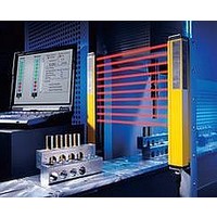
F39-EU1E Omron, F39-EU1E Datasheet - Page 66

F39-EU1E
Manufacturer Part Number
F39-EU1E
Description
F3S-B OPTIONAL PROGRAMMING KIT
Manufacturer
Omron
Datasheet
1.F39-EU1E.pdf
(865 pages)
Specifications of F39-EU1E
Leaded Process Compatible
No
Peak Reflow Compatible (260 C)
No
Light Curtain Type
Safety
Lead Free Status / RoHS Status
Contains lead / RoHS non-compliant
Lead Free Status / RoHS Status
Contains lead / RoHS non-compliant
- Current page: 66 of 865
- Download datasheet (35Mb)
Courtesy of Steven Engineering, Inc.-230 Ryan Way, South San Francisco, CA 94080-6370-Main Office: (650) 588-9200-Outside Local Area: (800) 258-9200-www.stevenengineering.com
Connection to Safety Light Curtain and Two Channels of Emergency Stop Switch Input (Manual Reset)
S1:
S2:
S3:
KM1 and KM2: Magnetic Contactors
M:
E1:
Note: 1. The F3SN-A’s EDM function and
* The Unit performs normal operation when
S3 is open and external diagnosis when it is
closed.
F39-JC@@C-L
2. Do not connect anything to
auxiliary outputs cannot be used.
terminals C1, D1, D2, E1, and E2.
Emitter
Black
Gray
Emergency stop switch
Reset switch (momentary action switch)
External test switch
3-phase motor
24-VDC Power Supply (S82K)
http://www.ia.omron.com/
F3SN-A/F3SN-B/F3SH-A Series
E1
F39-JC@@C-D
Receiver connector
Emitter connector
GND
Vcc
GND
Vcc
C1
S3
G1
*
G9SA-300-SC
D1
External
diagnosis
J1
D2
KM1 and KM2, NO contact
Limit switches (S1 and S2)
KM1 and KM2, NC contact
External test switch (S3)
K1 and K2, NO contact
K1 and K2, NC contact
Timing Chart
E1
Receiver
F3SN-A/-B/F3SH-A
Reset switch (S2)
Light interrupted
F
K3, NC contact
K3, NO contact
A1
Light incident
E2
E1
A2
S1
OSSD
+24 V
Emergency stop switch
0 V
T11
K1
T12
T21
K3
11
12
OSSD1
H1
K1
K2
T22
K3
OSSD2
21
22
(c)Copyright OMRON Corporation 2007 All Rights Reserved.
S2
K2
Y1
K3
K3
X1
K1
K2
KM1
KM2
K3
KM1
13
14
23
24
KM2
33
34
G9SA-300-SC
KM1
KM2
M
7
Related parts for F39-EU1E
Image
Part Number
Description
Manufacturer
Datasheet
Request
R

Part Number:
Description:
Pair Of Flat Mounting Brackets (transmitter & Receiver)
Manufacturer:
Omron

Part Number:
Description:
Pair Of Protective Shrouds (transmitter & Receiver)
Manufacturer:
Omron

Part Number:
Description:
G6S-2GLow Signal Relay
Manufacturer:
Omron Corporation
Datasheet:

Part Number:
Description:
Compact, Low-cost, SSR Switching 5 to 20 A
Manufacturer:
Omron Corporation
Datasheet:

Part Number:
Description:
Manufacturer:
Omron Corporation
Datasheet:


