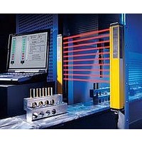
F39-EU1E Omron, F39-EU1E Datasheet - Page 364

F39-EU1E
Manufacturer Part Number
F39-EU1E
Description
F3S-B OPTIONAL PROGRAMMING KIT
Manufacturer
Omron
Datasheet
1.F39-EU1E.pdf
(865 pages)
Specifications of F39-EU1E
Leaded Process Compatible
No
Peak Reflow Compatible (260 C)
No
Light Curtain Type
Safety
Lead Free Status / RoHS Status
Contains lead / RoHS non-compliant
Lead Free Status / RoHS Status
Contains lead / RoHS non-compliant
- Current page: 364 of 865
- Download datasheet (35Mb)
Courtesy of Steven Engineering, Inc.-230 Ryan Way, South San Francisco, CA 94080-6370-Main Office: (650) 588-9200-Outside Local Area: (800) 258-9200-www.stevenengineering.com
Note: The above y values indicate the ratio ranges based on TT (total
2. Overtravel Dog
If the speed of the overtravel dog is comparatively high, make the rear
edge of the object smooth at an angle of 15 to 30 or make it in the
shape of a quadratic curve. Then lever shaking will be reduced.
Note: The above y values indicate the ratio ranges based on TT (total
Plunger Models
If the dog overrides the actuator, the front and rear of the dog may be
the same in shape, provided that the dog is not designed to be
separated from the actuator abruptly.
45
50
60 to 55
75 to 65
30
45
60
60 to 90
45
50
60 to 55
75 to 65
30
20
Dog speed: 0.5 m/s
travel). Therefore, the optimum pressing distance of the dog is
between 50% and 80% (or 50% and 70%).
travel). Therefore, the optimum pressing distance of the dog is
between 50% and 80% (or 50% and 70%).
Dog speed: 0.5 m/s max.
Dog speed: 0.5 m/s min.
60° max.
45
40
30 to 35
15 to 25
45
40
30 to 35
15 to 25
http://www.ia.omron.com/
φ
Lever set vertically
15 to 30 °
0.4
0.25
0.1
0.05 (low speed)
Roller Plunger
0.25
0.5
Change lever set angle (θ) according
to dog angle (φ)
V max. (m/s)
V max. (m/s)
φ
V
φ
0.5
0.6
1.3
2
0.5
0.6
1.3
2
V max. (m/s)
V max. (m/s)
2 m/s (High Speed)
φ
φ
0.8 (TT)
80% of total travel
0.6 to 0.8 (TT)
0.5 to 0.7 (TT)
0.5 to 0.8 (TT)
0.5 to 0.7 (TT)
0.5 to 0.8 (TT)
0.5 to 0.7 (TT)
y
y
y
y
Stroke Settings vs. Dog Movement Distance
Dog Surface
Others
a: Distance between reference line and actuator fulcrum
b: R cosθ
r: Roller radius
Y: Distance between reference line and bottom of dog
The following provides information on stroke settings based on the
movement distance of the dog instead of the actuator angle.
The following is the optimum stroke of the Limit Switch.
Optimum stroke: PT + {Rated OT x (0.7 to 1.0)}
The angle converted from the above:
The movement distance of the dog based on the optimum stroke is
expressed by the following formula.
Movement distance of dog
The distance between the reference line and the bottom of the dog
based on the optimum stroke is expressed by the following formula.
The surface of dog touching the actuator should be 6.3 S in quality
and hardened at approximately HV450.
For smooth operation of the actuator, apply molybdenum disulfide
grease to the actuator and the dog touching the actuator.
When using the Limit Switch with a long lever or long rod lever,
make sure that the lever is in the downward direction.
(c)Copyright OMRON Corporation 2007 All Rights Reserved.
Dog
φ: Dog angle
θ: Optimum stroke angle
R: Actuator length
X: Dog movement distance
Reference line
Dog
Precautions for All Safety Limit Switches
φ
PT: Pretravel
OT: Overtravel
70% to 100% of rated OT
Mounting hole
φ
1
+
2
Y
C-3
Related parts for F39-EU1E
Image
Part Number
Description
Manufacturer
Datasheet
Request
R

Part Number:
Description:
Pair Of Flat Mounting Brackets (transmitter & Receiver)
Manufacturer:
Omron

Part Number:
Description:
Pair Of Protective Shrouds (transmitter & Receiver)
Manufacturer:
Omron

Part Number:
Description:
G6S-2GLow Signal Relay
Manufacturer:
Omron Corporation
Datasheet:

Part Number:
Description:
Compact, Low-cost, SSR Switching 5 to 20 A
Manufacturer:
Omron Corporation
Datasheet:

Part Number:
Description:
Manufacturer:
Omron Corporation
Datasheet:


