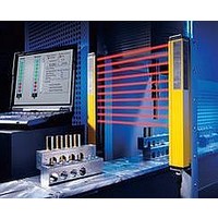
F39-EU1E Omron, F39-EU1E Datasheet - Page 169

F39-EU1E
Manufacturer Part Number
F39-EU1E
Description
F3S-B OPTIONAL PROGRAMMING KIT
Manufacturer
Omron
Datasheet
1.F39-EU1E.pdf
(865 pages)
Specifications of F39-EU1E
Leaded Process Compatible
No
Peak Reflow Compatible (260 C)
No
Light Curtain Type
Safety
Lead Free Status / RoHS Status
Contains lead / RoHS non-compliant
Lead Free Status / RoHS Status
Contains lead / RoHS non-compliant
- Current page: 169 of 865
- Download datasheet (35Mb)
Courtesy of Steven Engineering, Inc.-230 Ryan Way, South San Francisco, CA 94080-6370-Main Office: (650) 588-9200-Outside Local Area: (800) 258-9200-www.stevenengineering.com
➋ Selecting Relays
➀ Mounting Structure and Type of Protection
➋-➀-1 Type of Protection
If a Relay is selected that does not have the appropriate type of
protection for the atmosphere and the mounting conditions, it may
cause problems, such as contact failure.
Refer to the type of protection classifications shown in the following
table and select a Relay suitable to the atmosphere in which it is to be
used.
Classification by Type of Protection
➋-➀-2 Combining Relays and Sockets
Use OMRON Relays in combination with specified OMRON Sockets.
If the Relays are used with sockets from other manufacturers, it may
cause problems, such as abnormal heating at the mating point due to
differences in power capacity and mating properties.
➋-➀-3 Using Relays in Atmospheres Subject to Dust
If a Relay is used in an atmosphere subject to dust, dust will enter the
Relay, become lodged between contacts, and cause the circuit to fail
to close. Moreover, if conductive material such as wire clippings enter
the Relay, it will cause contact failure and short-circuiting.
Implement measures to protect against dust as required by the
application.
Mounting
structure
PCB-mounted
Relay
Type of
protection
Flux protection
Unsealed
http://www.ia.omron.com/
Item
Structure that
helps prevent
flux from
entering Relays
during soldering
Structure that
protects against
contact with
foreign material
by means of
enclosure in a
case (designed
for manual
soldering)
Features
G7SA
G7SB
G7S
Representative model
➁ Drive Circuits
➋-➁-1 Providing Power Continuously for Long Periods
If power is continuously provided to the coil for a long period,
deterioration of coil insulation will be accelerated due to heating of the
coil. Also see 3-2-7 Using with Infrequent Switching.
➋-➁-2 Operation Checks for Inspection and Maintenance
If a socket with an operation indicator is used, Relay status during
operation can be shown by means of the indicator, thereby facilitating
inspection and maintenance.
Note: The built-in indicator shows that power is being provided to the
➂ Loads
➋-➂-1 Contact Ratings
Contact ratings are generally shown for resistance loads and
inductive loads.
➋-➂-2 Using Relays with a Microload
Check the failure rate in the performance tables for individual
products.
Built-in indicator
coil. The indicator is not based on contact operation.
(c)Copyright OMRON Corporation 2008 All Rights Reserved.
Type
LED
Description
Some protection
(No large dust or
dirt particles
inside Relay.)
Dust and dirt
Precautions for All Relays
Atmosphere conditions
applicable models
Examples of
No protection
G7SA
Corrosive
G7S
gases
C-4
Related parts for F39-EU1E
Image
Part Number
Description
Manufacturer
Datasheet
Request
R

Part Number:
Description:
Pair Of Flat Mounting Brackets (transmitter & Receiver)
Manufacturer:
Omron

Part Number:
Description:
Pair Of Protective Shrouds (transmitter & Receiver)
Manufacturer:
Omron

Part Number:
Description:
G6S-2GLow Signal Relay
Manufacturer:
Omron Corporation
Datasheet:

Part Number:
Description:
Compact, Low-cost, SSR Switching 5 to 20 A
Manufacturer:
Omron Corporation
Datasheet:

Part Number:
Description:
Manufacturer:
Omron Corporation
Datasheet:


