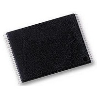
H27US08121B-TPCB HYNIX SEMICONDUCTOR, H27US08121B-TPCB Datasheet - Page 12

H27US08121B-TPCB
Manufacturer Part Number
H27US08121B-TPCB
Description
MEMORY, FLASH NAND 512MB, TSOP48
Manufacturer
HYNIX SEMICONDUCTOR
Datasheet
1.H27US08121B-TPCB.pdf
(43 pages)
Specifications of H27US08121B-TPCB
Memory Size
512Mbit
Access Time
45ns
Supply Voltage Range
2.7V To 3.6V
Memory Case Style
TSOP
No. Of Pins
48
Operating Temperature Range
0°C To +70°C
Package / Case
TSOP
Base Number
27
Memory Type
Flash - NAND
Memory Configuration
64M X 8, 32M X 16
Rohs Compliant
Yes
Lead Free Status / RoHS Status
Lead free / RoHS Compliant
COMMAND SET
All bus write operations to the device are interpreted by the Command Interface. The Commands are input on I/O
O
tions are selected by writing specific commands to the Command Register. The two-step command sequences for pro-
gram and erase operations are imposed to maximize data security.
The Commands are summarized in Table 5, Commands.
Table 5: Command Set
Note: (1). Any undefined command sequence will be ignored by the device.
input the addresses or input/output data are not shown.
DEVICE OPERATIONS
Pointer Operations
As the NAND Flash memories contain two different areas for x16 devices and three different areas for x8 devices (see
Figure 8) the read command codes (00h, 01h, 50h) are used to act as pointers to the different areas of the memory
array (they select the most significant column address).
The Read A and Read B commands act as pointers to the main memory area. Their use depends on the bus width of
the device.
to 255.
to 255, and the Read B command (01h) sets the pointer to Area B (the second half of the main area) that is Bytes 256
to 511.
In both the x8 and x16 devices the Read C command (50h), acts as a pointer to Area C (the spare memory area) that
is Bytes 512 to 527 or Words 256 to 263.
Once the Read A and Read C commands have been issued the pointer remains in the respective areas until another
Rev 0.6 / Oct. 2004
- In x16 devices the Read A command (00h) sets the pointer to Area A (the whole of the main area) that is Words 0
- In x8 devices the Read A command (00h) sets the pointer to Area A (the first half of the main area) that is Bytes 0
7
READ A
READ B
READ C
READ ELECTRINIC SIGNATURE
READ STATUS REGISTER
PAGE PROGRAM
COPY BACK PROGRAM
BLOCK ERASE
RESET
and are latched on the rising edge of Write Enable when the Command Latch Enable signal is high. Device opera-
(2). Bus Write Operation(1
FUNCTION
st
, 2
nd
and 3
1st CYCLE
00h
01h
50h
90h
70h
80h
00h
60h
FFh
rd
Cycle) : The bus cycles are only shown for issuing the codes. The cycles required to
512Mbit (64Mx8bit / 32Mx16bit) NAND Flash
2nd CYCLE
D0h
10h
8Ah
-
-
-
-
-
-
3rd CYCLE
10h
-
-
-
-
-
-
-
-
HY27US(08/16)121M Series
HY27SS(08/16)121M Series
Command accepted during busy
Yes
Yes
0
-I/
12


