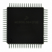
MC908LD64IFUE Freescale Semiconductor, MC908LD64IFUE Datasheet - Page 353

MC908LD64IFUE
Manufacturer Part Number
MC908LD64IFUE
Description
IC MCU 8BIT FOR LCD 64-QFP
Manufacturer
Freescale Semiconductor
Series
HC08r
Datasheet
1.MC908LD64IFUE.pdf
(362 pages)
Specifications of MC908LD64IFUE
Core Processor
HC08
Core Size
8-Bit
Speed
6MHz
Connectivity
I²C, USB
Peripherals
OSD, POR, PWM
Number Of I /o
39
Program Memory Size
60KB (60K x 8)
Program Memory Type
FLASH
Ram Size
2K x 8
Voltage - Supply (vcc/vdd)
3 V ~ 3.6 V
Data Converters
A/D 6x8b
Oscillator Type
Internal
Operating Temperature
0°C ~ 85°C
Package / Case
64-QFP
Processor Series
HC08LD
Core
HC08
Data Bus Width
8 bit
Data Ram Size
2 KB
Interface Type
I2C, USB
Maximum Clock Frequency
6 MHz
Number Of Programmable I/os
39
Number Of Timers
2
Maximum Operating Temperature
+ 85 C
Mounting Style
SMD/SMT
Development Tools By Supplier
FSICEBASE, M68CBL05CE
Minimum Operating Temperature
0 C
On-chip Adc
8 bit, 6 Channel
Lead Free Status / RoHS Status
Lead free / RoHS Compliant
Eeprom Size
-
Lead Free Status / Rohs Status
Details
Available stocks
Company
Part Number
Manufacturer
Quantity
Price
Company:
Part Number:
MC908LD64IFUE
Manufacturer:
Freescale Semiconductor
Quantity:
10 000
Part Number:
MC908LD64IFUE
Manufacturer:
FREESCALE
Quantity:
20 000
- Current page: 353 of 362
- Download datasheet (2Mb)
24.12.4 USB Signaling Levels
MC68HC908LD64
Freescale Semiconductor
Notes:
Differential “1”
Differential “0”
Data J State:
Low Speed
Full Speed
Data K State:
Low Speed
Full Speed
Idle State:
Low Speed
Full Speed
Resume State:
Low Speed
Full Speed
Start of Packet (SOP)
End of Packet (EOP)
Disconnect
Connect
Reset
1. The width of EOP is defined in bit times relative to the speed of transmission.
2. The width of EOP is defined in bit times relative to the device type receiving the EOP.
3. These times apply to an active device that is not in the suspend state.
(Upstream only)
(Upstream only)
(Downstream only)
Bus State
—
Rev. 3.0
Table 24-14. USB Signaling Levels
(D+) – (D–) > 200 mV and D+ or D– > V
(D+) – (D–) < –200 mV and D+ or D– > V
Differential “0”
Differential “1”
Differential “1”
Differential “0”
Differential “0” and D– > V
Differential “1” and D+ > V
Differential “1” and D+ > V
Differential “0” and D– > V
Data lines switch from Idle to K State
D+ and D– < V
—
—
D+ and D– < V
times
time
From Originating Driver
(1)
Electrical Specifications
followed by an Idle for 1 bit
SE
SE
(min) for 2 bit
for ≥10 ms
SE
SE
SE
SE
(max.) and D+ < V
(max.) and D+ < V
(max.) and D– < V
(max.) and D– < V
Signaling Levels
D+ and D– < V
D+ and D– < V
D+ or D– > V
D+ and D– < V
SE
SE
time
(must be recognized within 5.5
µs)
(min.)
USB DC Electrical Characteristics
(min.)
(3)
(2)
SE
SE
SE
SE
followed by a J State
(min.)
(min.)
(min.)
(min.)
At Receiver
SE
Electrical Specifications
SE
SE
SE
(max) for ≥ 2.5 µs
(min) for ≥ 1 bit
(max) for ≥ 2.5 µs
(min) for ≥ 2.5 µs
Data Sheet
353
Related parts for MC908LD64IFUE
Image
Part Number
Description
Manufacturer
Datasheet
Request
R
Part Number:
Description:
Manufacturer:
Freescale Semiconductor, Inc
Datasheet:
Part Number:
Description:
Manufacturer:
Freescale Semiconductor, Inc
Datasheet:
Part Number:
Description:
Manufacturer:
Freescale Semiconductor, Inc
Datasheet:
Part Number:
Description:
Manufacturer:
Freescale Semiconductor, Inc
Datasheet:
Part Number:
Description:
Manufacturer:
Freescale Semiconductor, Inc
Datasheet:
Part Number:
Description:
Manufacturer:
Freescale Semiconductor, Inc
Datasheet:
Part Number:
Description:
Manufacturer:
Freescale Semiconductor, Inc
Datasheet:
Part Number:
Description:
Manufacturer:
Freescale Semiconductor, Inc
Datasheet:
Part Number:
Description:
Manufacturer:
Freescale Semiconductor, Inc
Datasheet:
Part Number:
Description:
Manufacturer:
Freescale Semiconductor, Inc
Datasheet:
Part Number:
Description:
Manufacturer:
Freescale Semiconductor, Inc
Datasheet:
Part Number:
Description:
Manufacturer:
Freescale Semiconductor, Inc
Datasheet:
Part Number:
Description:
Manufacturer:
Freescale Semiconductor, Inc
Datasheet:
Part Number:
Description:
Manufacturer:
Freescale Semiconductor, Inc
Datasheet:
Part Number:
Description:
Manufacturer:
Freescale Semiconductor, Inc
Datasheet:


