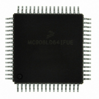
MC908LD64IFUE Freescale Semiconductor, MC908LD64IFUE Datasheet - Page 231

MC908LD64IFUE
Manufacturer Part Number
MC908LD64IFUE
Description
IC MCU 8BIT FOR LCD 64-QFP
Manufacturer
Freescale Semiconductor
Series
HC08r
Datasheet
1.MC908LD64IFUE.pdf
(362 pages)
Specifications of MC908LD64IFUE
Core Processor
HC08
Core Size
8-Bit
Speed
6MHz
Connectivity
I²C, USB
Peripherals
OSD, POR, PWM
Number Of I /o
39
Program Memory Size
60KB (60K x 8)
Program Memory Type
FLASH
Ram Size
2K x 8
Voltage - Supply (vcc/vdd)
3 V ~ 3.6 V
Data Converters
A/D 6x8b
Oscillator Type
Internal
Operating Temperature
0°C ~ 85°C
Package / Case
64-QFP
Processor Series
HC08LD
Core
HC08
Data Bus Width
8 bit
Data Ram Size
2 KB
Interface Type
I2C, USB
Maximum Clock Frequency
6 MHz
Number Of Programmable I/os
39
Number Of Timers
2
Maximum Operating Temperature
+ 85 C
Mounting Style
SMD/SMT
Development Tools By Supplier
FSICEBASE, M68CBL05CE
Minimum Operating Temperature
0 C
On-chip Adc
8 bit, 6 Channel
Lead Free Status / RoHS Status
Lead free / RoHS Compliant
Eeprom Size
-
Lead Free Status / Rohs Status
Details
Available stocks
Company
Part Number
Manufacturer
Quantity
Price
Company:
Part Number:
MC908LD64IFUE
Manufacturer:
Freescale Semiconductor
Quantity:
10 000
Part Number:
MC908LD64IFUE
Manufacturer:
FREESCALE
Quantity:
20 000
- Current page: 231 of 362
- Download datasheet (2Mb)
15.5.6 Multi-Master IIC Data Receive Register (MMDRR)
MC68HC908LD64
Freescale Semiconductor
—
Rev. 3.0
Address
If the calling master does not return an acknowledge bit (MMRXAK = 1),
the module will release the SDA line for master to generate a "stop" or
"repeated start" condition. The data in the MMDTR will not be transferred
to the output circuit until the next calling from a master. The transmit
buffer empty flag remains cleared (MMTXBE = 0).
In master mode, the data in MMDTR will be transferred to the output
circuit when:
If the slave does not return an acknowledge bit (MMRXAK = 1), the
master will generate a "stop" or "repeated start" condition. The data in
the MMDTR will not be transferred to the output circuit. The transmit
buffer empty flag remains cleared (MMTXBE = 0).
The sequence of events for slave transmit and master transmit are
illustrated in
When the MMIIC module is enabled, MMEN = 1, data in this read-only
register depends on whether module is in master or slave mode.
Reset:
Read: MMRD7 MMRD6 MMRD5 MMRD4 MMRD3 MMRD2 MMRD1 MMRD0
Write:
Figure 15-7. Multi-Master IIC Data Receive Register (MMDRR)
•
•
:
the module receives an acknowledge bit (MMRXAK = 0), after
setting master transmit mode (MMRW = 0), and the calling
address has been transmitted; or
the previous data in the output circuit has be transmitted and the
receiving slave returns an acknowledge bit, indicated by a
received acknowledge bit (MMRXAK = 0).
$006F
Bit 7
Multi-Master IIC Interface (MMIIC)
0
Figure
d
= Unimplemente
6
0
15-8.
5
0
4
0
3
0
Multi-Master IIC Interface (MMIIC)
Multi-Master IIC Registers
2
0
1
0
Data Sheet
Bit 0
0
231
Related parts for MC908LD64IFUE
Image
Part Number
Description
Manufacturer
Datasheet
Request
R
Part Number:
Description:
Manufacturer:
Freescale Semiconductor, Inc
Datasheet:
Part Number:
Description:
Manufacturer:
Freescale Semiconductor, Inc
Datasheet:
Part Number:
Description:
Manufacturer:
Freescale Semiconductor, Inc
Datasheet:
Part Number:
Description:
Manufacturer:
Freescale Semiconductor, Inc
Datasheet:
Part Number:
Description:
Manufacturer:
Freescale Semiconductor, Inc
Datasheet:
Part Number:
Description:
Manufacturer:
Freescale Semiconductor, Inc
Datasheet:
Part Number:
Description:
Manufacturer:
Freescale Semiconductor, Inc
Datasheet:
Part Number:
Description:
Manufacturer:
Freescale Semiconductor, Inc
Datasheet:
Part Number:
Description:
Manufacturer:
Freescale Semiconductor, Inc
Datasheet:
Part Number:
Description:
Manufacturer:
Freescale Semiconductor, Inc
Datasheet:
Part Number:
Description:
Manufacturer:
Freescale Semiconductor, Inc
Datasheet:
Part Number:
Description:
Manufacturer:
Freescale Semiconductor, Inc
Datasheet:
Part Number:
Description:
Manufacturer:
Freescale Semiconductor, Inc
Datasheet:
Part Number:
Description:
Manufacturer:
Freescale Semiconductor, Inc
Datasheet:
Part Number:
Description:
Manufacturer:
Freescale Semiconductor, Inc
Datasheet:


