Chameleon-AVR Nurve Networks, Chameleon-AVR Datasheet - Page 73
Chameleon-AVR
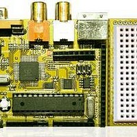
Manufacturer Part Number
Chameleon-AVR
Description
MCU, MPU & DSP Development Tools AVR8 & PROPELLER DEV SYSTEM (SBC)
Manufacturer
Nurve Networks
Datasheet
1.CHAMELEON-AVR.pdf
(268 pages)
Specifications of Chameleon-AVR
Processor To Be Evaluated
AVR 328P
Data Bus Width
8 bit
Interface Type
USB, VGA, PS/2, I2C, ISP, SPI
Operating Supply Voltage
3.3 V, 5 V
Lead Free Status / RoHS Status
Lead free / RoHS Compliant


PHASE_INC that for a given PWM frequency (256,000 in this case) and a desired output signal frequency along with a
specific number of data table elements will make the whole thing work. Here’s the final math:
Given,
1. A complete sine waveform has 65536 data entries in our virtual table and 256 in the real table.
2. The PWM frequency is 256K.
In other words,
Now, let’s compute PHASE_INC,
That is, the PHASE_INC is the rate at which we need to increment thru the data table to maintain the relationship so that
the output is changing at the rate of the signal frequency. Now, plugging this all in together and moving things around a
bit:
And of course PHASE_ACC is simply set to 0 to begin with when the algorithm starts. As an example, let’s compute some
values and see if it works. First let’s try a 1KHz signal and see what we get:
So this means that we add 256 to the phase accumulator each PWM cycle, then use the upper 8-bits of the phase
accumulator as the index, let’s try it a few cycles as see of it works:
Referring to Table 14.2, we see that each cycle of the PWM the PHASE_ACC is incremented by 1 and the next element
in the 256 element sine table is accessed, thus the table is cycled thru at a rate of 256,000 / 256 = 1,000 Hz! Perfect!
Now, let’s try another example where the frequency is higher than what we could sustain with our more crude approach at
the beginning of the section with only a counter and not using the accumulator and fixed point approach. Let’s try to
synthesize a 2550 Hz signal.
Now, this is a decimal number which will be truncated during the fixed point math to 652, but this is fine, that’s only an
error or:
NUM_INCREMENTS = The number of times that the PWM signal increments thru the final signal table in ONE
complete wave cycle. This is shown in Figure 14.7.
NUM_INCREMENTS
PHASE_INC = 65536 / NUM_INCREMENTS
PHASE_INC = 65536 * signal frequency / PWM frequency.
PHASE_INC = 65536 * 1KHz / 256,000 = 256.
PHASE_INC = 65536 * 2550 / 256,000 = 652.8
Iteration
0
1
2
3
4
5
6
7
.
.
255
Table 14.2 – Test of PWM algorithm at 1KHz with PHASE_INC of 256.
= signal period / PWM period
= PWM frequency / signal frequency
PHASE_INC
256
256
256
256
256
256
256
256
256
PHASE_ACC PHASE_ACC (upper 8-bits)
0
256
512
768
1024
1280
1536
1792
65280
© 2009 NURVE NETWORKS LLC “Exploring the Chameleon AVR 8-Bit”
0
1
2
3
4
5
6
7
255
73
Related parts for Chameleon-AVR
Image
Part Number
Description
Manufacturer
Datasheet
Request
R

Part Number:
Description:
MCU, MPU & DSP Development Tools PIC24 & PROPELLER DEV SYSTEM (SBC)
Manufacturer:
Nurve Networks
Datasheet:

Part Number:
Description:
MCU, MPU & DSP Development Tools AVR8 VIDEO GAME DEV SYSTEM (SBC)
Manufacturer:
Nurve Networks

Part Number:
Description:
MCU, MPU & DSP Development Tools PIC24 VIDEO GAME DEV SYSTEM (SBC)
Manufacturer:
Nurve Networks