Chameleon-AVR Nurve Networks, Chameleon-AVR Datasheet - Page 35
Chameleon-AVR
Manufacturer Part Number
Chameleon-AVR
Description
MCU, MPU & DSP Development Tools AVR8 & PROPELLER DEV SYSTEM (SBC)
Manufacturer
Nurve Networks
Datasheet
1.CHAMELEON-AVR.pdf
(268 pages)
Specifications of Chameleon-AVR
Processor To Be Evaluated
AVR 328P
Data Bus Width
8 bit
Interface Type
USB, VGA, PS/2, I2C, ISP, SPI
Operating Supply Voltage
3.3 V, 5 V
Lead Free Status / RoHS Status
Lead free / RoHS Compliant


© 2009 NURVE NETWORKS LLC “Exploring the Chameleon AVR 8-Bit”
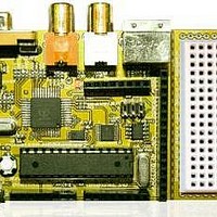
8.0 Parallax Propeller Subsystem
Figure 8.1 – The Propeller Subsystem.
2
Figure 8.1 depicts the entire Propeller chip subsystem. It consists of the Propeller chip itself (QFP package), the 64K I
C
serial EEPROM for program storage, a single LED, and the Propeller Port I/O header at J8. Additionally, the Propeller is
clocked by a 5 MHz nominal XTAL at X1. The only thing interesting about the design is the free Propeller Local Port at J8,
it connects to Propeller I/O pins P0…P7. Thus, you can connect other devices to this header, or potentially drive another
NTSC/PAL/VGA video device or you can just use it at 8 more digital I/O ports. Lastly, the Propeller chip only needs a 32K
EEPROM to load its runtime image into its local SRAM, however, we are using a 64K EEPROM which not only allows 2
images, but potentially a single image with additional program assets like graphics, sound, or code.
8.1 The Propeller Local 8-Bit I/O Port
The Propeller Local Port is an 8-bit port consisting of 8 free digital I/O pins from P0…P7 on the Propeller chip. You can do
anything you want with the port. You can even power devices from the port by using some of the pins as power and virtual
ground. The Propeller can source up to 40mA per pin, so if you tie 2 lines together and set them HIGH, you can source up
to 80mA, more than enough for most applications.
35
Related parts for Chameleon-AVR
Image
Part Number
Description
Manufacturer
Datasheet
Request
R

Part Number:
Description:
MCU, MPU & DSP Development Tools PIC24 & PROPELLER DEV SYSTEM (SBC)
Manufacturer:
Nurve Networks
Datasheet:

Part Number:
Description:
MCU, MPU & DSP Development Tools AVR8 VIDEO GAME DEV SYSTEM (SBC)
Manufacturer:
Nurve Networks

Part Number:
Description:
MCU, MPU & DSP Development Tools PIC24 VIDEO GAME DEV SYSTEM (SBC)
Manufacturer:
Nurve Networks