Chameleon-AVR Nurve Networks, Chameleon-AVR Datasheet - Page 177
Chameleon-AVR
Manufacturer Part Number
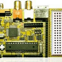
Chameleon-AVR
Description
MCU, MPU & DSP Development Tools AVR8 & PROPELLER DEV SYSTEM (SBC)
Manufacturer
Nurve Networks
Datasheet
1.CHAMELEON-AVR.pdf
(268 pages)
Specifications of Chameleon-AVR
Processor To Be Evaluated
AVR 328P
Data Bus Width
8 bit
Interface Type
USB, VGA, PS/2, I2C, ISP, SPI
Operating Supply Voltage
3.3 V, 5 V
Lead Free Status / RoHS Status
Lead free / RoHS Compliant


© 2009 NURVE NETWORKS LLC “Exploring the Chameleon AVR 8-Bit”
Tile Map and Playfield Size
Now, let’s take a look at the specifics of this tile map engine. Referring to Figure 22.1, the tile map starts off 32x24
displayed on the NTSC screen. This is the physical resolution and never changes. That is, we can never display more
than 32x24 tiles on the physical screen. However, the “playfield” can be much larger to facilitate scrolling or page flipping.
The engine supports horizontal tile pitches of 32, 64, 128, and 256. Thus, horizontally, the playfield can be quite large.
Vertically, there are no power of 2 restraints, so you can make the vertical pitch anything you want (as long as you don’t
run out of memory). The tile map itself starts at the declaration tile_maps (make sure to take a look yourself) in the driver
portion of code and is controlled by changing the global variable tile_map_base_ptr_parm in the register interface.
The tile map represents what’s on the screen physically and the entire playfield virtually, which might be much larger than
the physical screen of 32x24. The tile map pointer above points to the start of the tile map, but how the tiles are
interpreted, that is, how many per row is controlled by a register that controls the setup of the tile mode. This variable in
the driver is called tile_map_control_parm and controls a number of interesting things, here’s the initial default setup
code for this variable on driver start up:
So the format of this 4-byte value is
The top and bottom overscan colors (these are the colors on the top and bottom of your TV screen, usually black) are in a
simple luma/chroma format which we will discuss in the section below on color palettes. The horizontal and vertical
smooth scroll are encoded as 4-bits each, but only vertical smooth scrolling works currently and the valid values are 0..7.
Finally, the playfield width is controlled with this register as well. It can be 32, 64, 128, or 256 tiles wide, a subset of
powers of 2.
Now, this register is accessed via a number of separate “shadow” registers in the global register interface, but I wanted
you to see this in the code, so when we discuss the registers they are familiar.
Tile Map Entry Format
Each tile map entry is a 2-bytes In the following format:
The low byte is the actual tile character index 0..255, and the high byte is the palette index 0..255. However, in most
cases you won’t have this many tiles or palettes. In fact, initially there are only 16 palettes 0..15 and there are 144 bitmaps
extracted from file font file c64_font_05_16b.bmp followed by 16 blanks for user definition of course you can overwrite
these as well with direct memory access if you wish to. The font file was hand made and based on the Commodore 64
and Atari 800 fonts as well as some extra characters for fun. The font file is located on the CD here:
DVD-ROM:\ CHAM_AVR \ TOOLS \ GRAPHICS \ c64_font_05_16b.bmp
Figure 22.2 shows a screen shot of the font file for reference.
177
Related parts for Chameleon-AVR
Image
Part Number
Description
Manufacturer
Datasheet
Request
R

Part Number:
Description:
MCU, MPU & DSP Development Tools PIC24 & PROPELLER DEV SYSTEM (SBC)
Manufacturer:
Nurve Networks
Datasheet:

Part Number:
Description:
MCU, MPU & DSP Development Tools AVR8 VIDEO GAME DEV SYSTEM (SBC)
Manufacturer:
Nurve Networks

Part Number:
Description:
MCU, MPU & DSP Development Tools PIC24 VIDEO GAME DEV SYSTEM (SBC)
Manufacturer:
Nurve Networks