Chameleon-AVR Nurve Networks, Chameleon-AVR Datasheet - Page 157
Chameleon-AVR
Manufacturer Part Number
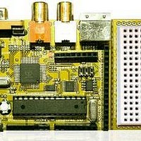
Chameleon-AVR
Description
MCU, MPU & DSP Development Tools AVR8 & PROPELLER DEV SYSTEM (SBC)
Manufacturer
Nurve Networks
Datasheet
1.CHAMELEON-AVR.pdf
(268 pages)
Specifications of Chameleon-AVR
Processor To Be Evaluated
AVR 328P
Data Bus Width
8 bit
Interface Type
USB, VGA, PS/2, I2C, ISP, SPI
Operating Supply Voltage
3.3 V, 5 V
Lead Free Status / RoHS Status
Lead free / RoHS Compliant


A START condition is always followed by the (unique) 7-bit slave address along with a single bit signifying the “Data
Direction” either read or write. The Slave device addressed acknowledges the Master by holding SDA low for one clock
cycle. If the Master does not receive an acknowledgement the transfer is terminated. Depending of the Data Direction
bit, the Master or Slave now transmits 8-bits of data on the SDA line. The receiving device then acknowledges the data.
Figure 19.5 shows what happens during data transmission following the initial START and addressing phases.
Multiple bytes can be transferred in one direction before a repeated START or a STOP condition is issued by the Master.
The transfer is terminated when the Master issues a “STOP condition”. A STOP condition is defined by a low to high
transition on the SDA line while the SCL is high. Confusing isn’t it?
If a Slave device cannot handle incoming data until it has performed some other function, it can hold SCL low to force the
Master into a “wait-state” for as long as it needs to. All data packets transmitted on the I
of 8 data bits, and an acknowledge bit. Now, during a data transfer, the Master generates the clock and the START and
STOP conditions, while the receiver is responsible for acknowledging the reception. An Acknowledge (ACK) is signaled by
the receiver pulling the SDA line low during the 9th clock cycle pulse on SCL. If the receiver leaves the SDA line high, a
“NACK” (no ACK) is signaled, and the transfer is not completed.
In conclusion, I
state machine, bus contention and so forth. However, the AVR 644P has built in I
it all much easier to implement. Setting up the registers is still a bit challenging and you have to read the documentation
quite a bit to get the hang of it. I suggest you review the following references for a more complete treatise on I
Now, let’s move onto the SPI and I
hardware. Moreover, you may wish to develop much higher level functionality yourself. If you do, make note that the “SD
card” library uses the SPI functions in this module, so you will have to emulate their functionality and linker names.
DVD-ROM:\ CHAM_AVR \ DOCS \ I2C \ avr315_TWI_I2C.pdf
DVD-ROM:\ CHAM_AVR \ DOCS \ I2C \ twi_programming.htm
DVD-ROM:\ CHAM_AVR \ DOCS \ I2C \ I2C_bus.pdf
2
C is a lot more complex that SPI, and writing a software implementation is a lot harder as well due to the
Figure 19.4 – Timing waveforms for I
Figure 19.5 – Timing waveforms for I2C data transmission.
2
C library module that implements a very thin layer of software on top of the built in
© 2009 NURVE NETWORKS LLC “Exploring the Chameleon AVR 8-Bit”
2
C “START Condition”.
2
C hardware as mentioned which makes
2
C bus are 9 bits long, consisting
2
C:
157
Related parts for Chameleon-AVR
Image
Part Number
Description
Manufacturer
Datasheet
Request
R

Part Number:
Description:
MCU, MPU & DSP Development Tools PIC24 & PROPELLER DEV SYSTEM (SBC)
Manufacturer:
Nurve Networks
Datasheet:

Part Number:
Description:
MCU, MPU & DSP Development Tools AVR8 VIDEO GAME DEV SYSTEM (SBC)
Manufacturer:
Nurve Networks

Part Number:
Description:
MCU, MPU & DSP Development Tools PIC24 VIDEO GAME DEV SYSTEM (SBC)
Manufacturer:
Nurve Networks