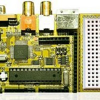
Chameleon-AVR Nurve Networks, Chameleon-AVR Datasheet - Page 103

Chameleon-AVR
Manufacturer Part Number
Chameleon-AVR
Description
MCU, MPU & DSP Development Tools AVR8 & PROPELLER DEV SYSTEM (SBC)
Manufacturer
Nurve Networks
Datasheet
1.CHAMELEON-AVR.pdf
(268 pages)
Specifications of Chameleon-AVR
Processor To Be Evaluated
AVR 328P
Data Bus Width
8 bit
Interface Type
USB, VGA, PS/2, I2C, ISP, SPI
Operating Supply Voltage
3.3 V, 5 V
Lead Free Status / RoHS Status
Lead free / RoHS Compliant
- Current page: 103 of 268
- Download datasheet (17Mb)
However, all of the fuse settings need to be exactly as depicted in the figure. Additionally, make sure the three
checkboxes at the bottom of the window are all checked; Auto read, Smart warning, and Verify after programming.
When your fuse settings are all exactly as shown in the figure above, then the bottommost window will show you the
actual binary encoding which should be:
If you weren’t using this tool and using another tool that needed the actual binary bit values for the “extended”, “high”,
and “low” fuse bits then you could use these values.
Once you have all the fuse bits and drop downs set to mimic the settings in Figure 15.38, you could click the <Program>
button to write the fuses if you wish. This will not program the chip (since we don’t want to do that yet), but it will program
the fuse bits only. Go ahead and click <Program> to write the fuse bits, if everything goes well, you should see the text
output window at the bottom of the tool scroll some informational strings and you should see a lot of “OK!”’s displayed. If
you don’t try it again.
Normally, you do not have to do this when programming the chip. The programming process will reset the fuse bits as
well, but it can’t hurt to make sure. If your chip ever acts strangely always go and investigate the fuse bit settings and see
if they are correct (as shown in Figure 15.38).
We are almost there, the very last tab of interest is the “Lockbits” tab, select this tab as shown in Figure 15.39.
BODLEVEL
JTAGEN
SPIEN
BOOTSZ
SUT_CKSEL
Fuse Bank Name
EXTENDED
HIGH
LOW
Figure 15.39 – The AVR ISP MKII control panel’s “Lockbits” tab.
- Brown out control (disabled).
- JTAG Enable.
- SPI Enable.
- Boot FLASH size (size = 1024, address =$3C00)
- Clock Select (8Mhz, Start up time 16CK/14CK + 0ms).
Value
0xFF
0xDA
0xDF
© 2009 NURVE NETWORKS LLC “Exploring the Chameleon AVR 8-Bit”
103
Related parts for Chameleon-AVR
Image
Part Number
Description
Manufacturer
Datasheet
Request
R

Part Number:
Description:
MCU, MPU & DSP Development Tools PIC24 & PROPELLER DEV SYSTEM (SBC)
Manufacturer:
Nurve Networks
Datasheet:

Part Number:
Description:
MCU, MPU & DSP Development Tools AVR8 VIDEO GAME DEV SYSTEM (SBC)
Manufacturer:
Nurve Networks

Part Number:
Description:
MCU, MPU & DSP Development Tools PIC24 VIDEO GAME DEV SYSTEM (SBC)
Manufacturer:
Nurve Networks


