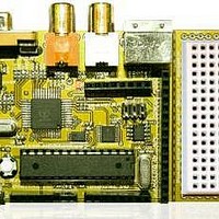
Chameleon-AVR Nurve Networks, Chameleon-AVR Datasheet - Page 65

Chameleon-AVR
Manufacturer Part Number
Chameleon-AVR
Description
MCU, MPU & DSP Development Tools AVR8 & PROPELLER DEV SYSTEM (SBC)
Manufacturer
Nurve Networks
Datasheet
1.CHAMELEON-AVR.pdf
(268 pages)
Specifications of Chameleon-AVR
Processor To Be Evaluated
AVR 328P
Data Bus Width
8 bit
Interface Type
USB, VGA, PS/2, I2C, ISP, SPI
Operating Supply Voltage
3.3 V, 5 V
Lead Free Status / RoHS Status
Lead free / RoHS Compliant
- Current page: 65 of 268
- Download datasheet (17Mb)
J4
J4
J4
J4
J6
J6
J6
J5
J6
J6
J6
J6
J7
J7
J7
J7
J7
J7
J7
J7
Note 1: Power pins 5VCC, 33VCC, GND don’t actually connect to the AVR, but to the system power lines which in-turn
are electrically connected to the AVR’s AVCC, VCC, and GND respectively.
Note 2: VIN is connected to the 5V regulator’s input pin. This signal reflects the input analog voltage plugged into the 9V
DC power jack. If only the USB power is plugged in this signal will be floating or near ground.
14.0 Audio Hardware
There is no dedicated audio hardware inside the AVR chip nor the Propeller chip, therefore we have to rely on “software
techniques” to create sound for the system. However, knowing that software is going to be used to generate sound we
can add a little analog circuitry to “help” the audio software out and allow us to use certain common techniques for
generating sounds. The Propeller does have counters on board and can generate PWM signals, thus the audio drivers
typically leverage these hardware elements. Thus, for most audio applications that connect to a Propeller chip all you
need is a typical PWM “integrator” or “low pass” filter. The Chameleon employs such a hardware design as shown in
Figure 14.1.
Referring to the circuit, we see that the signal AUDIO_MONO (I/O P24, pin 31 on the Propeller) is an input into the
network. This signal is passed thru a low pass filter consisting of a resistor (R14 @ 1K ohm) and a capacitor (C15 @
0.1uF). Note these reference designators may change in the future, but the point is there is an R/C network here. Moving
Figure 14.1 – The analog audio hardware on the Chameleon AVR.
DPIN3
DPIN2
DPIN1
DPIN0
SPI_SS1n
SPI_SS0n
AIN5
AIN4
AIN3
AIN2
AIN1
AIN0
GND
GND
RESn
33VCC
5VCC
GND
GND
VIN
2
1
1
1
1
1
1
© 2009 NURVE NETWORKS LLC “Exploring the Chameleon AVR 8-Bit”
5
4
3
2
NA
NA
28
27
26
25
24
23
8,22
8,22
1
NA
20
8,22
8,22
NA
PD3 (PCINT19 / OC2B / INT1)
PD2 (PCINT18 / INT0)
PD1 (PCINT17 / TXD)
PD0 (PCINT16 / RXD)
NA
NA
PC5 (ADC5 / SCL / PCINT13)
PC4 (ADC4 / SDA / PCIN12)
PC3 (ADC3 / PCINT11)
PC2 (ADC2 / PCINT10)
PC1 (ADC1 / PCINT9)
PC0 (ADC0 / PCINT8)
GND
GND
PC6 (PCINT14 / RESETn)
NA
VCC
GND
GND
NA
65
Related parts for Chameleon-AVR
Image
Part Number
Description
Manufacturer
Datasheet
Request
R

Part Number:
Description:
MCU, MPU & DSP Development Tools PIC24 & PROPELLER DEV SYSTEM (SBC)
Manufacturer:
Nurve Networks
Datasheet:

Part Number:
Description:
MCU, MPU & DSP Development Tools AVR8 VIDEO GAME DEV SYSTEM (SBC)
Manufacturer:
Nurve Networks

Part Number:
Description:
MCU, MPU & DSP Development Tools PIC24 VIDEO GAME DEV SYSTEM (SBC)
Manufacturer:
Nurve Networks


