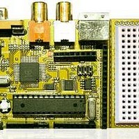
Chameleon-AVR Nurve Networks, Chameleon-AVR Datasheet - Page 156

Chameleon-AVR
Manufacturer Part Number
Chameleon-AVR
Description
MCU, MPU & DSP Development Tools AVR8 & PROPELLER DEV SYSTEM (SBC)
Manufacturer
Nurve Networks
Datasheet
1.CHAMELEON-AVR.pdf
(268 pages)
Specifications of Chameleon-AVR
Processor To Be Evaluated
AVR 328P
Data Bus Width
8 bit
Interface Type
USB, VGA, PS/2, I2C, ISP, SPI
Operating Supply Voltage
3.3 V, 5 V
Lead Free Status / RoHS Status
Lead free / RoHS Compliant
- Current page: 156 of 268
- Download datasheet (17Mb)
© 2009 NURVE NETWORKS LLC “Exploring the Chameleon AVR 8-Bit”
2
and the I
C bus is not without its shortcomings. First, it is nowhere near as fast as SPI. SPI can operate at 25 MHz and
2
even up to 50 MHz. I
C on the other hand averages around 100 KHz+, with 400 KHz being fast with many new devices
2
supporting 1Mhz. Thus, SPI is at least 25 times faster. But, that’s not the whole story. The added overhead that I
C
2
protocol attaches to communication (addressing, commands, etc.) slow the protocol even more. Thus, I
C devices tend to
find there way into “slow” peripherals where speed isn’t and/or issue, but addressing many of them. For example, serial
2
memories, sensors, etc. where the device itself is slow, the 100-400 KHz average speed of I
C is more than enough.
However, SPI devices you will see in very high speed applications even video and audio.
2
Figure 19.4 shows an architectural diagram of how the I
C bus is laid out in relation to the master device, and the slaves
on the line.
Figure 19.3 – I2C bus layout.
2
Electrically, the I
C bus consists of any number of “masters” and “slaves” on the bus. Masters initiate communication
while slaves listen and respond. Masters can transmit and receive from a slave, but a slave can not initiate
communications. Additionally, to enforce that masters are in charge, the clock line SCL can only be controlled by a
master furthermore placing the slave(s) into a passive role. Moreover, so that multiple devices can be connected to the
same 2-signal bus from an electrical point of view, both SDA and SCL are open drain, thus “pull-up” resistors must be
connected from SDA and SCL to Vcc via a 5-10K resistor on both lines. Note that with the SPI bus, all SPI devices share
the MISO (master input), MOSI (master output), and SCLK (serial clock) lines; however, the CS or chip select lines for
each device controls the selection of the target device (not an address), and when a device is selected its bus is active
while any other de-selected devices go tristate. Thus, the I2C bus is always active and arbitration is achieved thru an
open drain design where SDA and SCL can only be pulled down by the master, and SDA alone by the slave. Then
2
addressing is achieved by a 7-bit address sent down the I
C bus to all devices, only the listening device with the
matching address responds and communication begin. Let’s discuss this process more in detail.
2
19.2.1 Understanding I
C Bus States
2
The I
C protocol is rather complex compared to SPI protocol. In fact, there is no “SPI protocol” per se. SPI is a simple
serial packet much like RS-232. The only “protocol” that SPI devices have are inherent in the devices themselves and
2
what the bytes sent and received mean. I
C on the other hand has this very complex arbitration system to handle
2
multiple Masters on the bus, this is facilitated via the electrical design as well as a “state machine” that I
C is based on.
2
Considering this, I
C is rather complex. We are only briefly going to cover some of the high level concepts of the protocol
and its primary states; START, and STOP.
To begin with, data is transfer is always initiated by a Master device (remember Slaves can only respond to Masters). A
high to low transition on the SDA line while SCL is high is defined to be a “START condition” or a “repeated START
2
condition”. Everything begins with the “START” condition, that’s the first thing to remember with I
C. Figure 19.4 below
show the timing waveforms for this event.
156
Related parts for Chameleon-AVR
Image
Part Number
Description
Manufacturer
Datasheet
Request
R

Part Number:
Description:
MCU, MPU & DSP Development Tools PIC24 & PROPELLER DEV SYSTEM (SBC)
Manufacturer:
Nurve Networks
Datasheet:

Part Number:
Description:
MCU, MPU & DSP Development Tools AVR8 VIDEO GAME DEV SYSTEM (SBC)
Manufacturer:
Nurve Networks

Part Number:
Description:
MCU, MPU & DSP Development Tools PIC24 VIDEO GAME DEV SYSTEM (SBC)
Manufacturer:
Nurve Networks


