Chameleon-AVR Nurve Networks, Chameleon-AVR Datasheet - Page 128
Chameleon-AVR
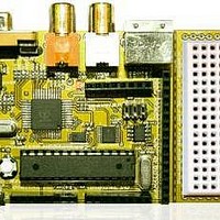
Manufacturer Part Number
Chameleon-AVR
Description
MCU, MPU & DSP Development Tools AVR8 & PROPELLER DEV SYSTEM (SBC)
Manufacturer
Nurve Networks
Datasheet
1.CHAMELEON-AVR.pdf
(268 pages)
Specifications of Chameleon-AVR
Processor To Be Evaluated
AVR 328P
Data Bus Width
8 bit
Interface Type
USB, VGA, PS/2, I2C, ISP, SPI
Operating Supply Voltage
3.3 V, 5 V
Lead Free Status / RoHS Status
Lead free / RoHS Compliant


16.0 Chameleon Inter-Processor Architecture Overview
In this section, we are going to go into a bit of detail in relation to the software engineering techniques that the
Chameleon’s duel processor architecture is based on. This section isn’t necessary to use the Chameleon, but its
necessary to understand the design more completely.
Referring to Figure 16.1, the Chameleon’s Propeller co-processor has a number of connections to various media I/O
devices. These include NTSC/PAL composite video, VGA, audio out, serial (not shown), and PS/2 keyboard/mouse
devices. This uses up a minimum of (5) processing cores, leaving us (3) cores for other things and for future expansion.
Of course, two cores are used for the Master Control Program that runs on the Propeller as well as the SPI virtual driver.
Thus we are left with (1) core ultimately for expansion unless we modify the default Propeller driver. As shown in the
figure, the NTSC signal is on Pin 12,13,14, VGA is on pins 16…23, audio is on pin 10, the PS/2 keyboard/mouse is
connected to pins 26,27 and finally the serial is on pins 30,31. Basically, this is a standard Propeller Board Rev. C/D pin
map.
TIP
This pin map was selected to keep the Propeller sub-system very compatible with
Propeller development boards, so the Chameleon could double as a Propeller
development kit!
Figure 16.1 - System level modular schematic.
© 2009 NURVE NETWORKS LLC “Exploring the Chameleon AVR 8-Bit”
128
Related parts for Chameleon-AVR
Image
Part Number
Description
Manufacturer
Datasheet
Request
R

Part Number:
Description:
MCU, MPU & DSP Development Tools PIC24 & PROPELLER DEV SYSTEM (SBC)
Manufacturer:
Nurve Networks
Datasheet:

Part Number:
Description:
MCU, MPU & DSP Development Tools AVR8 VIDEO GAME DEV SYSTEM (SBC)
Manufacturer:
Nurve Networks

Part Number:
Description:
MCU, MPU & DSP Development Tools PIC24 VIDEO GAME DEV SYSTEM (SBC)
Manufacturer:
Nurve Networks