Chameleon-AVR Nurve Networks, Chameleon-AVR Datasheet - Page 26
Chameleon-AVR
Manufacturer Part Number
Chameleon-AVR
Description
MCU, MPU & DSP Development Tools AVR8 & PROPELLER DEV SYSTEM (SBC)
Manufacturer
Nurve Networks
Datasheet
1.CHAMELEON-AVR.pdf
(268 pages)
Specifications of Chameleon-AVR
Processor To Be Evaluated
AVR 328P
Data Bus Width
8 bit
Interface Type
USB, VGA, PS/2, I2C, ISP, SPI
Operating Supply Voltage
3.3 V, 5 V
Lead Free Status / RoHS Status
Lead free / RoHS Compliant


© 2009 NURVE NETWORKS LLC “Exploring the Chameleon AVR 8-Bit”
1.31 Propeller Core (COG) Video Hardware
Lastly, let’s talk about the video hardware for a moment. Probably the coolest thing about the Propeller chip is that each
core has a little state machine that can stream video data out. These little devices are called Video Streaming Units or
VSUs and every core has one. Thus, you can in theory drive 8 different video signals at the same time. The VSUs are not
graphics engines, GPUs, even 2D stuff. They are nothing more than serializers that send bytes out to port. However, they
send bytes out at a specific rate and the analog signals they can generate can be timed to synthesize NTSC or PAL
signals including blanking, sync, chroma, and color burst signals. In essence, with each core you can use software to set
up the VSU units, then the unit will send out data representing one portion or “chunk” of the video signal, then you feed it
more. Therefore, you have to know how to generate NTSC, PAL, or VGA yourself, but the VSU helps and offloads a lot of
the timing and critical coding you would need to do usually.
Alas, once again, you don’t have to worry about this. Myself, and numerous other programmers have written countless
video drivers for the Propeller chip. Everything from bitmap graphics, text modes, to sprite engines. So if you want
graphics, you just find a driver, add it to your program and then make calls to it. More on this later when we learn how to
modify the Chameleon drivers at the end of the manual.
1.4. System Startup and Reset Details
The Chameleon AVR has no operating system or external peripherals that need initialization, thus the AVR 328P more or
less is the entire “system”. When the AVR powers up out of reset, it will either load the boot loader (if there is one), or
begin execution from the primary application memory of the FLASH. The initial configuration of the chip is defined by the
“fuse” bit settings which are controlled by the programming of the chip. In our case, the fuse settings are mostly default,
with the Arduino boot loader and set to clock from an external high speed xtal. We will discuss exact details when we get
to the software and IDE configuration. Once the AVR 328P boots and starts executing code, whatever is in the application
program area is executed, simple as that.
While this is all happening the Propeller chip boots as well and will start up doing whatever its programmed to do.
Normally, this will be to load the default SPI driver system and “wait” for commands from the AVR. However, there is no
reason the Propeller couldn’t be programmed with a game, or other application and ignore the commands on the agreed
to SPI interface pins. Therefore, the Chameleon can be used as a stand alone AVR or Propeller controller if you wish.
However, the point is to use them together than leverage their strong points; the AVR’s simple programming model,
C/C++ support, huge library of software and customer base along with the multicore support of the Propeller and its ability
to run multiple tasks at once as well as its special ability to generate video
With that in mind, now let’s discuss every one of the hardware modules in the design.
Part I - Hardware Design Primer
In this section, we are going to cover every one of the Chameleon AVR’s hardware sub-sections, so you can get an idea
of what’s going on and how the systems and signals are routed. Taken as a whole the Chameleon is rather complex, but
as you will see, each individual sub-system is rather straightforward. Let’s begin with a birds eye view of the entire system
schematic on the next page in landscape mode (Figure 2.1a). Please take a good look at it, and see if you can locate the
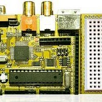
AVR, Propeller, FLASH memory, EEPROM, and power supplies to help with our discussions. Then right under it in Figure
2.1(b) is a PCB view so you can see where everything is as well as a clear view of the I/O headers in black and white with
high contrast. The board is so small its, a bit hard to see things.
Figure 2.1(a) – The complete Chameleon AVR 8-bit schematic.
26
Related parts for Chameleon-AVR
Image
Part Number
Description
Manufacturer
Datasheet
Request
R

Part Number:
Description:
MCU, MPU & DSP Development Tools PIC24 & PROPELLER DEV SYSTEM (SBC)
Manufacturer:
Nurve Networks
Datasheet:

Part Number:
Description:
MCU, MPU & DSP Development Tools AVR8 VIDEO GAME DEV SYSTEM (SBC)
Manufacturer:
Nurve Networks

Part Number:
Description:
MCU, MPU & DSP Development Tools PIC24 VIDEO GAME DEV SYSTEM (SBC)
Manufacturer:
Nurve Networks