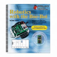
28125 Parallax Inc, 28125 Datasheet - Page 262

28125
Manufacturer Part Number
28125
Description
TEXT ROBOTICS
Manufacturer
Parallax Inc
Datasheet
1.28125.pdf
(360 pages)
Specifications of 28125
Title
Robotics with the Boe-Bot
Product
Microcontroller Accessories
Lead Free Status / RoHS Status
Not applicable / Not applicable
- Current page: 262 of 360
- Download datasheet (5Mb)
The command
into low power mode.
Your Turn – Testing LED Brightness
Series Resistance and IR Detection Range
We now know that less series resistance will make an LED glow more brightly. A
reasonable hypothesis would be that brighter IR LEDs can make it possible to detect
objects that are further away.
Your Turn – Testing IR LED Range
√
√
√
√
√
√
√
√
√
√
√
√
Note how brightly the LED in the circuit connected to P1 is glowing with the
220 Ω resistor.
Replace the 220 Ω resistor connected to P1 and the right LED’s cathode with a
470 Ω resistor.
Note now how brightly the LED glows.
Repeat for a 2 kΩ resistor.
Repeat once more with a 4.7 kΩ resistor.
Replace the 4.7 kΩ resistor with the 220 Ω resistor before moving on to the next
portion of this activity.
Explain in your own words the relationship between LED brightness and series
resistance.
Open and run TestIrPairsAndIndicators.bs2 (from page 244).
Verify that both detectors are working properly.
With a ruler, measure the furthest distance from the IR LED that a sheet of paper
facing the IR LED can be detected, with the 1 kΩ resistors in place, and record
your data in Table 7-2.
Replace the 1 kΩ resistors that connect P2 and P8 to the IR LED anodes with 4.7
kΩ resistors.
Determine the furthest distance at which the same sheet of paper is detected, and
record your data.
Remember to disconnect power before you make changes to a circuit. Remember
also that the same program will run again when you reconnect power, so you can pick up
right where you left off with each test.
STOP
is used here rather than
END
, since
END
would put the BASIC Stamp
Related parts for 28125
Image
Part Number
Description
Manufacturer
Datasheet
Request
R

Part Number:
Description:
Microcontroller Modules & Accessories DISCONTINUED BY PARALLAX
Manufacturer:
Parallax Inc

Part Number:
Description:
BOOK UNDERSTANDING SIGNALS
Manufacturer:
Parallax Inc
Datasheet:

Part Number:
Description:
COMPETITION RING FOR SUMOBOT
Manufacturer:
Parallax Inc
Datasheet:

Part Number:
Description:
TEXT INFRARED REMOTE FOR BOE-BOT
Manufacturer:
Parallax Inc
Datasheet:

Part Number:
Description:
BOARD EXPERIMENT+LCD NX-1000
Manufacturer:
Parallax Inc
Datasheet:

Part Number:
Description:
CONTROLLER 16SERVO MOTOR CONTROL
Manufacturer:
Parallax Inc
Datasheet:

Part Number:
Description:
BASIC STAMP LOGIC ANALYZER
Manufacturer:
Parallax Inc
Datasheet:

Part Number:
Description:
IC MCU 2K FLASH 50MHZ SO-18
Manufacturer:
Parallax Inc
Datasheet:


