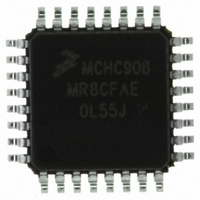
MCHC908MR8CFAE Freescale Semiconductor, MCHC908MR8CFAE Datasheet - Page 137

MCHC908MR8CFAE
Manufacturer Part Number
MCHC908MR8CFAE
Description
IC MCU 8K FLASH 8MHZ PWM 32-LQFP
Manufacturer
Freescale Semiconductor
Series
HC08r
Datasheet
1.MCHC908MR8VFAE.pdf
(372 pages)
Specifications of MCHC908MR8CFAE
Core Processor
HC08
Core Size
8-Bit
Speed
8MHz
Connectivity
SCI
Peripherals
LVD, POR, PWM
Number Of I /o
16
Program Memory Size
8KB (8K x 8)
Program Memory Type
FLASH
Ram Size
256 x 8
Voltage - Supply (vcc/vdd)
4.5 V ~ 5.5 V
Data Converters
A/D 7x10b
Oscillator Type
Internal
Operating Temperature
-40°C ~ 85°C
Package / Case
32-LQFP
Controller Family/series
HC08
No. Of I/o's
16
Ram Memory Size
256Byte
Cpu Speed
8MHz
No. Of Timers
2
Rohs Compliant
Yes
Processor Series
HC08MR
Core
HC08
Data Bus Width
8 bit
Data Ram Size
64 B
Interface Type
SCI, SPI
Maximum Clock Frequency
8 MHz
Number Of Programmable I/os
32
Number Of Timers
4
Operating Supply Voltage
0 V to 5 V
Maximum Operating Temperature
+ 85 C
Mounting Style
SMD/SMT
Development Tools By Supplier
FSICEBASE, M68CBL05CE
Minimum Operating Temperature
- 40 C
On-chip Adc
8 bit, 8 Channel
Lead Free Status / RoHS Status
Lead free / RoHS Compliant
Eeprom Size
-
Lead Free Status / Rohs Status
Details
Available stocks
Company
Part Number
Manufacturer
Quantity
Price
Company:
Part Number:
MCHC908MR8CFAE
Manufacturer:
Freescale Semiconductor
Quantity:
10 000
- Current page: 137 of 372
- Download datasheet (4Mb)
8.11.4 Reaction Time Calculation
MC68HC908MR8 — Rev 4.1
Freescale Semiconductor
NOTE:
This equation does not always yield a commonly available capacitor
size, so round to the nearest available size. If the value is between two
different sizes, choose the higher value for better stability. Choosing the
lower size may seem attractive for acquisition time improvement, but the
PLL can become unstable. Also, always choose a capacitor with a tight
tolerance (±20 percent or better) and low dissipation.
The actual acquisition and lock times can be calculated using the
equations here. These equations yield nominal values under these
conditions:
The K factor in the equations is derived from internal PLL parameters.
K
K
8.4.2.2 Acquisition and Tracking
Inverse proportionality between the lock time and the reference
frequency
In automatic bandwidth control mode, the acquisition and lock times are
quantized into units based on the reference frequency, see
Manual and Automatic PLL Bandwidth
clock cycles, n
tracking mode entry tolerance, ∆
ACQ
TRK
•
•
•
•
is the K factor when the PLL is configured in tracking mode. See
is the K factor when the PLL is configured in acquisition mode, and
Correct selection of filter capacitor, C
Filter Capacitor
Room temperature operation
Negligible external leakage on CGMXFC
Negligible noise
Clock Generator Module (CGM)
ACQ
, is required to ascertain that the PLL is within the
t
ACQ
t
AL
t
Lock
=
=
TRK
V
---------------- -
=
f
V
---------------- -
RDV
f
DDA
RDV
DDA
t
Modes.
ACQ
, before exiting acquisition mode. A
----------------
K
+
-----------------
K
Acquisition/Lock Time Specifications
TRK
t
ACQ
Modes. A certain number of
4
AL
8
F
; see
Clock Generator Module (CGM)
8.11.3 Choosing a
Technical Data
8.4.2.3
137
Related parts for MCHC908MR8CFAE
Image
Part Number
Description
Manufacturer
Datasheet
Request
R
Part Number:
Description:
Manufacturer:
Freescale Semiconductor, Inc
Datasheet:
Part Number:
Description:
Manufacturer:
Freescale Semiconductor, Inc
Datasheet:
Part Number:
Description:
Manufacturer:
Freescale Semiconductor, Inc
Datasheet:
Part Number:
Description:
Manufacturer:
Freescale Semiconductor, Inc
Datasheet:
Part Number:
Description:
Manufacturer:
Freescale Semiconductor, Inc
Datasheet:
Part Number:
Description:
Manufacturer:
Freescale Semiconductor, Inc
Datasheet:
Part Number:
Description:
Manufacturer:
Freescale Semiconductor, Inc
Datasheet:
Part Number:
Description:
Manufacturer:
Freescale Semiconductor, Inc
Datasheet:
Part Number:
Description:
Manufacturer:
Freescale Semiconductor, Inc
Datasheet:
Part Number:
Description:
Manufacturer:
Freescale Semiconductor, Inc
Datasheet:
Part Number:
Description:
Manufacturer:
Freescale Semiconductor, Inc
Datasheet:
Part Number:
Description:
Manufacturer:
Freescale Semiconductor, Inc
Datasheet:
Part Number:
Description:
Manufacturer:
Freescale Semiconductor, Inc
Datasheet:
Part Number:
Description:
Manufacturer:
Freescale Semiconductor, Inc
Datasheet:
Part Number:
Description:
Manufacturer:
Freescale Semiconductor, Inc
Datasheet:


