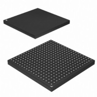
AT91SAM9M10-CU Atmel, AT91SAM9M10-CU Datasheet - Page 773

AT91SAM9M10-CU
Manufacturer Part Number
AT91SAM9M10-CU
Description
IC MCU 16/32BIT ARM9 324TFBGA
Manufacturer
Atmel
Series
AT91SAMr
Specifications of AT91SAM9M10-CU
Core Processor
ARM9
Core Size
16/32-Bit
Speed
400MHz
Connectivity
EBI/EMI, Ethernet, I²C, SPI, SSC, UART/USART, USB
Peripherals
AC'97, DMA, LCD, POR, PWM, WDT
Number Of I /o
160
Program Memory Size
64KB (64K x 8)
Program Memory Type
ROM
Ram Size
128K x 8
Voltage - Supply (vcc/vdd)
0.9 V ~ 1.1 V
Data Converters
A/D 8x10b
Oscillator Type
Internal
Operating Temperature
-40°C ~ 85°C
Package / Case
324-TFBGA
Processor Series
AT91SAMx
Core
ARM926EJ-S
Data Bus Width
32 bit
Data Ram Size
32 KB
Interface Type
2-Wire, SPI, USART
Maximum Clock Frequency
133 MHz
Number Of Programmable I/os
5
Number Of Timers
2 x 16 bit
Operating Supply Voltage
1.65 V to 3.6 V
Maximum Operating Temperature
+ 85 C
Mounting Style
SMD/SMT
3rd Party Development Tools
JTRACE-ARM-2M, MDK-ARM, RL-ARM, ULINK2
Development Tools By Supplier
AT91SAM-ICE, AT91-ISP, AT91SAM9M10-G45-EK
Controller Family/series
AT91
No. Of I/o's
160
Ram Memory Size
64KB
Cpu Speed
400MHz
No. Of Timers
2
Rohs Compliant
Yes
Cpu Family
AT91
Device Core
ARM926EJ-S
Device Core Size
32b
Frequency (max)
400MHz
Total Internal Ram Size
64KB
# I/os (max)
160
Number Of Timers - General Purpose
7
Operating Supply Voltage (typ)
1.8/2.5/3.3V
Operating Supply Voltage (max)
1.1/1.95/3.6V
Operating Supply Voltage (min)
0.9/1.65/1.8/3V
On-chip Adc
8-chx10-bit
Instruction Set Architecture
RISC
Operating Temp Range
-40C to 85C
Operating Temperature Classification
Industrial
Mounting
Surface Mount
Pin Count
324
Package Type
TFBGA
Lead Free Status / RoHS Status
Lead free / RoHS Compliant
Eeprom Size
-
Lead Free Status / Rohs Status
Lead free / RoHS Compliant
Available stocks
Company
Part Number
Manufacturer
Quantity
Price
Company:
Part Number:
AT91SAM9M10-CU
Manufacturer:
Atmel
Quantity:
996
- Current page: 773 of 1404
- Download datasheet (22Mb)
36.4.7
36.4.8
36.4.9
6355B–ATARM–21-Jun-10
Broadcast Address
Hash Addressing
Copy All Frames (or Promiscuous Mode)
The sequence above shows the beginning of an Ethernet frame. Byte order of transmission is
from top to bottom as shown. For a successful match to specific address 1, the following
address matching registers must be set up:
And for a successful match to the Type ID register, the following should be set up:
The broadcast address of 0xFFFFFFFFFFFF is recognized if the ‘no broadcast’ bit in the net-
work configuration register is zero.
The hash address register is 64 bits long and takes up two locations in the memory map. The
least significant bits are stored in hash register bottom and the most significant bits in hash reg-
ister top.
The unicast hash enable and the multicast hash enable bits in the network configuration register
enable the reception of hash matched frames. The destination address is reduced to a 6-bit
index into the 64-bit hash register using the following hash function. The hash function is an
exclusive or of every sixth bit of the destination address.
hash_index[5] = da[5] ^ da[11] ^ da[17] ^ da[23] ^ da[29] ^ da[35] ^ da[41] ^ da[47]
hash_index[4] = da[4] ^ da[10] ^ da[16] ^ da[22] ^ da[28] ^ da[34] ^ da[40] ^ da[46]
hash_index[3] = da[3] ^ da[09] ^ da[15] ^ da[21] ^ da[27] ^ da[33] ^ da[39] ^ da[45]
hash_index[2] = da[2] ^ da[08] ^ da[14] ^ da[20] ^ da[26] ^ da[32] ^ da[38] ^ da[44]
hash_index[1] = da[1] ^ da[07] ^ da[13] ^ da[19] ^ da[25] ^ da[31] ^ da[37] ^ da[43]
hash_index[0] = da[0] ^ da[06] ^ da[12] ^ da[18] ^ da[24] ^ da[30] ^ da[36] ^ da[42]
da[0] represents the least significant bit of the first byte received, that is, the multicast/unicast
indicator, and da[47] represents the most significant bit of the last byte received.
If the hash index points to a bit that is set in the hash register, then the frame is matched accord-
ing to whether the frame is multicast or unicast.
A multicast match is signalled if the multicast hash enable bit is set. da[0] is 1 and the hash index
points to a bit set in the hash register.
A unicast match is signalled if the unicast hash enable bit is set. da[0] is 0 and the hash index
points to a bit set in the hash register.
To receive all multicast frames, the hash register should be set with all ones and the multicast
hash enable bit should be set in the network configuration register.
If the copy all frames bit is set in the network configuration register, then all non-errored frames
are copied to memory. For example, frames that are too long, too short, or have FCS errors or
rx_er asserted during reception are discarded and all others are received. Frames with FCS
errors are copied to memory if bit 19 in the network configuration register is set.
• Base address + 0x98 0x87654321 (Bottom)
• Base address + 0x9C 0x0000CBA9 (Top)
• Base address + 0xB8 0x00004321
AT91SAM9M10
773
Related parts for AT91SAM9M10-CU
Image
Part Number
Description
Manufacturer
Datasheet
Request
R

Part Number:
Description:
MCU, MPU & DSP Development Tools KICKSTART KIT FOR AT91SAM9 PLUS
Manufacturer:
IAR Systems

Part Number:
Description:
DEV KIT FOR AVR/AVR32
Manufacturer:
Atmel
Datasheet:

Part Number:
Description:
INTERVAL AND WIPE/WASH WIPER CONTROL IC WITH DELAY
Manufacturer:
ATMEL Corporation
Datasheet:

Part Number:
Description:
Low-Voltage Voice-Switched IC for Hands-Free Operation
Manufacturer:
ATMEL Corporation
Datasheet:

Part Number:
Description:
MONOLITHIC INTEGRATED FEATUREPHONE CIRCUIT
Manufacturer:
ATMEL Corporation
Datasheet:

Part Number:
Description:
AM-FM Receiver IC U4255BM-M
Manufacturer:
ATMEL Corporation
Datasheet:

Part Number:
Description:
Monolithic Integrated Feature Phone Circuit
Manufacturer:
ATMEL Corporation
Datasheet:

Part Number:
Description:
Multistandard Video-IF and Quasi Parallel Sound Processing
Manufacturer:
ATMEL Corporation
Datasheet:

Part Number:
Description:
High-performance EE PLD
Manufacturer:
ATMEL Corporation
Datasheet:

Part Number:
Description:
8-bit Flash Microcontroller
Manufacturer:
ATMEL Corporation
Datasheet:

Part Number:
Description:
2-Wire Serial EEPROM
Manufacturer:
ATMEL Corporation
Datasheet:


