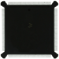
MC68332GCEH16 Freescale Semiconductor, MC68332GCEH16 Datasheet - Page 74

MC68332GCEH16
Manufacturer Part Number
MC68332GCEH16
Description
IC MCU 32BIT 16MHZ 132-PQFP
Manufacturer
Freescale Semiconductor
Series
M683xxr
Specifications of MC68332GCEH16
Core Processor
CPU32
Core Size
32-Bit
Speed
16MHz
Connectivity
EBI/EMI, SCI, SPI, UART/USART
Peripherals
POR, PWM, WDT
Number Of I /o
15
Program Memory Type
ROMless
Ram Size
2K x 8
Voltage - Supply (vcc/vdd)
4.5 V ~ 5.5 V
Oscillator Type
Internal
Operating Temperature
-40°C ~ 85°C
Package / Case
132-QFP
Cpu Family
68K/M683xx
Device Core
ColdFire
Device Core Size
32b
Frequency (max)
16MHz
Interface Type
QSPI/SCI/UART
Program Memory Size
Not Required
Total Internal Ram Size
2KB
# I/os (max)
15
Number Of Timers - General Purpose
16
Operating Supply Voltage (typ)
5V
Operating Supply Voltage (max)
5.5V
Operating Supply Voltage (min)
4.5V
Instruction Set Architecture
RISC
Operating Temp Range
-40C to 85C
Operating Temperature Classification
Industrial
Mounting
Surface Mount
Pin Count
132
Package Type
PQFP
Controller Family/series
68K
No. Of I/o's
15
Ram Memory Size
2KB
Cpu Speed
16MHz
No. Of Timers
16
Embedded Interface Type
QSPI, SCI, UART
Digital Ic Case Style
PQFP
Rohs Compliant
Yes
Processor Series
M683xx
Core
CPU32
Data Bus Width
32 bit
Data Ram Size
2 KB
Maximum Clock Frequency
16 MHz
Number Of Programmable I/os
15
Number Of Timers
16
Maximum Operating Temperature
+ 85 C
Mounting Style
SMD/SMT
Minimum Operating Temperature
- 40 C
Lead Free Status / RoHS Status
Lead free / RoHS Compliant
Eeprom Size
-
Program Memory Size
-
Data Converters
-
Lead Free Status / Rohs Status
Compliant
Available stocks
Company
Part Number
Manufacturer
Quantity
Price
Company:
Part Number:
MC68332GCEH16
Manufacturer:
Freescale Semiconductor
Quantity:
10 000
4.5.5.3 Retry Operation
4.5.5.4 Halt Operation
4-34
Immediately after assertion of a second BERR, the MCU halts and drives the HALT
line low. Only a reset can restart a halted MCU. However, bus arbitration can still occur
(refer to 4.5.6 External Bus Arbitration). A bus error or address error that occurs after
exception processing has been completed (during the execution of the exception han-
dler routine, or later) does not cause a double bus fault. The MCU continues to retry
the same bus cycle as long as the external hardware requests it.
When an external device asserts BERR and HALT during a bus cycle, the MCU enters
the retry sequence. A delayed retry can also occur. The MCU terminates the bus cycle,
places the AS and DS signals in their inactive state, and does not begin another bus
cycle until the BERR and HALT signals are negated by external logic. After a synchro-
nization delay, the MCU retries the previous cycle using the same address, function
codes, data (for a write), and control signals. The BERR signal should be negated be-
fore S2 of the read cycle to ensure correct operation of the retried cycle.
If BR, BERR, and HALT are all asserted on the same cycle, the EBI will enter the rerun
sequence but first relinquishes the bus to an external master. Once the external mas-
ter returns the bus and negates BERR and HALT, the EBI runs the previous bus cycle.
This feature allows an external device to correct the problem that caused the bus error
and then try the bus cycle again.
The MCU retries any read or write cycle of an indivisible read-modify-write operation
separately; RMC remains asserted during the entire retry sequence. The MCU will not
relinquish the bus while RMC is asserted. Any device that requires the MCU to give up
the bus and retry a bus cycle during a read-modify-write cycle must assert BERR and
BR only (HALT must remain negated). The bus error handler software should examine
the read-modify-write bit in the special status word and take the appropriate action to
resolve this type of fault when it occurs.
When HALT is asserted while BERR is not asserted, the MCU halts external bus ac-
tivity after negation of DSACK. The MCU may complete the current word transfer in
progress. For a long-word to byte transfer, this could be after S2 or S4. For a word to
byte transfer, activity ceases after S2.
Negating and reasserting HALT according to timing requirements provides single-step
(bus cycle to bus cycle) operation. The HALT signal affects external bus cycles only,
so that a program that does not use external bus can continue executing. During dy-
namically-sized 8-bit transfers, external bus activity may not stop at the next cycle
boundary. Occurrence of a bus error while HALT is asserted causes the CPU32 to ini-
tiate a retry sequence.
When the MCU completes a bus cycle while the HALT signal is asserted, the data bus
goes to high-impedance state and the AS and DS signals are driven to their inactive
states. Address, function code, size, and read/write signals remain in the same state.
Freescale Semiconductor, Inc.
For More Information On This Product,
SYSTEM INTEGRATION MODULE
Go to: www.freescale.com
USER’S MANUAL
MC68332


