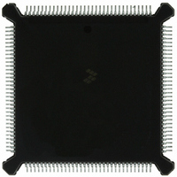
MC68332GCEH16 Freescale Semiconductor, MC68332GCEH16 Datasheet - Page 161

MC68332GCEH16
Manufacturer Part Number
MC68332GCEH16
Description
IC MCU 32BIT 16MHZ 132-PQFP
Manufacturer
Freescale Semiconductor
Series
M683xxr
Specifications of MC68332GCEH16
Core Processor
CPU32
Core Size
32-Bit
Speed
16MHz
Connectivity
EBI/EMI, SCI, SPI, UART/USART
Peripherals
POR, PWM, WDT
Number Of I /o
15
Program Memory Type
ROMless
Ram Size
2K x 8
Voltage - Supply (vcc/vdd)
4.5 V ~ 5.5 V
Oscillator Type
Internal
Operating Temperature
-40°C ~ 85°C
Package / Case
132-QFP
Cpu Family
68K/M683xx
Device Core
ColdFire
Device Core Size
32b
Frequency (max)
16MHz
Interface Type
QSPI/SCI/UART
Program Memory Size
Not Required
Total Internal Ram Size
2KB
# I/os (max)
15
Number Of Timers - General Purpose
16
Operating Supply Voltage (typ)
5V
Operating Supply Voltage (max)
5.5V
Operating Supply Voltage (min)
4.5V
Instruction Set Architecture
RISC
Operating Temp Range
-40C to 85C
Operating Temperature Classification
Industrial
Mounting
Surface Mount
Pin Count
132
Package Type
PQFP
Controller Family/series
68K
No. Of I/o's
15
Ram Memory Size
2KB
Cpu Speed
16MHz
No. Of Timers
16
Embedded Interface Type
QSPI, SCI, UART
Digital Ic Case Style
PQFP
Rohs Compliant
Yes
Processor Series
M683xx
Core
CPU32
Data Bus Width
32 bit
Data Ram Size
2 KB
Maximum Clock Frequency
16 MHz
Number Of Programmable I/os
15
Number Of Timers
16
Maximum Operating Temperature
+ 85 C
Mounting Style
SMD/SMT
Minimum Operating Temperature
- 40 C
Lead Free Status / RoHS Status
Lead free / RoHS Compliant
Eeprom Size
-
Program Memory Size
-
Data Converters
-
Lead Free Status / Rohs Status
Compliant
Available stocks
Company
Part Number
Manufacturer
Quantity
Price
Company:
Part Number:
MC68332GCEH16
Manufacturer:
Freescale Semiconductor
Quantity:
10 000
7.4.4 Pulse-Width Modulation (PWM)
7.4.5 Synchronized Pulse-Width Modulation (SPWM)
7.4.6 Period Measurement with Additional Transition Detect (PMA)
7.4.7 Period Measurement with Missing Transition Detect (PMM)
7.4.8 Position-Synchronized Pulse Generator (PSP)
MC68332
USER’S MANUAL
The TPU can generate a pulse-width modulation waveform with any duty cycle from
zero to 100% (within the resolution and latency capability of the TPU). To define the
PWM, the CPU provides one parameter that indicates the period and another param-
eter that indicates the high time. Updates to one or both of these parameters can direct
the waveform change to take effect immediately, or coherently beginning at the next
low-to-high transition of the pin.
The TPU generates a PWM waveform in which the CPU can change the period and/
or high time at any time. When synchronized to a time function on a second channel,
the synchronized PWM low-to-high transitions have a time relationship to transitions
on the second channel.
This function and the following function are used primarily in toothed-wheel speed-
sensing applications, such as monitoring rotational speed of an engine. The period
measurement with additional transition detect function allows for a special-purpose
23-bit period measurement. It can detect the occurrence of an additional transition
(caused by an extra tooth on the sensed wheel) indicated by a period measurement
that is less than a programmable ratio of the previous period measurement.
Once detected, this condition can be counted and compared to a programmable num-
ber of additional transitions detected before TCR2 is reset to $FFFF. Alternatively, a
byte at an address specified by a channel parameter can be read and used as a flag.
A nonzero value of the flag indicates that TCR2 is to be reset to $FFFF once the next
additional transition is detected
Period measurement with missing transition detect allows a special-purpose 23-bit pe-
riod measurement. It detects the occurrence of a missing transition (caused by a miss-
ing tooth on the sensed wheel), indicated by a period measurement that is greater than
a programmable ratio of the previous period measurement. Once detected, this con-
dition can be counted and compared to a programmable number of additional transi-
tions detected before TCR2 is reset to $FFFF. In addition, one byte at an address
specified by a channel parameter can be read and used as a flag. A nonzero value of
the flag indicates that TCR2 is to be reset to $FFFF once the next missing transition
is detected.
Any channel of the TPU can generate an output transition or pulse, which is a projec-
tion in time based on a reference period previously calculated on another channel.
Both TCRs are used in this algorithm: TCR1 is internally clocked, and TCR2 is clocked
by a position indicator in the user's device. An example of a TCR2 clock source is a
sensor that detects special teeth on the flywheel of an automobile using PMA or PMM.
The teeth are placed at known degrees of engine rotation; hence, TCR2 is a coarse
representation of engine degrees, i.e., each count represents some number of de-
grees.
Freescale Semiconductor, Inc.
For More Information On This Product,
Go to: www.freescale.com
TIME PROCESSOR UNIT
7-7


