MC68332GCEH16 Freescale Semiconductor, MC68332GCEH16 Datasheet - Page 124
MC68332GCEH16
Manufacturer Part Number
MC68332GCEH16
Description
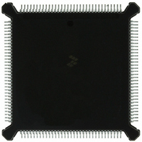
IC MCU 32BIT 16MHZ 132-PQFP
Manufacturer
Freescale Semiconductor
Series
M683xxr
Specifications of MC68332GCEH16
Core Processor
CPU32
Core Size
32-Bit
Speed
16MHz
Connectivity
EBI/EMI, SCI, SPI, UART/USART
Peripherals
POR, PWM, WDT
Number Of I /o
15
Program Memory Type
ROMless
Ram Size
2K x 8
Voltage - Supply (vcc/vdd)
4.5 V ~ 5.5 V
Oscillator Type
Internal
Operating Temperature
-40°C ~ 85°C
Package / Case
132-QFP
Cpu Family
68K/M683xx
Device Core
ColdFire
Device Core Size
32b
Frequency (max)
16MHz
Interface Type
QSPI/SCI/UART
Program Memory Size
Not Required
Total Internal Ram Size
2KB
# I/os (max)
15
Number Of Timers - General Purpose
16
Operating Supply Voltage (typ)
5V
Operating Supply Voltage (max)
5.5V
Operating Supply Voltage (min)
4.5V
Instruction Set Architecture
RISC
Operating Temp Range
-40C to 85C
Operating Temperature Classification
Industrial
Mounting
Surface Mount
Pin Count
132
Package Type
PQFP
Controller Family/series
68K
No. Of I/o's
15
Ram Memory Size
2KB
Cpu Speed
16MHz
No. Of Timers
16
Embedded Interface Type
QSPI, SCI, UART
Digital Ic Case Style
PQFP
Rohs Compliant
Yes
Processor Series
M683xx
Core
CPU32
Data Bus Width
32 bit
Data Ram Size
2 KB
Maximum Clock Frequency
16 MHz
Number Of Programmable I/os
15
Number Of Timers
16
Maximum Operating Temperature
+ 85 C
Mounting Style
SMD/SMT
Minimum Operating Temperature
- 40 C
Lead Free Status / RoHS Status
Lead free / RoHS Compliant
Eeprom Size
-
Program Memory Size
-
Data Converters
-
Lead Free Status / Rohs Status
Compliant
Available stocks
Company
Part Number
Manufacturer
Quantity
Price
Company:

Part Number:
MC68332GCEH16
Manufacturer:
Freescale Semiconductor
Quantity:
10 000


6.2 QSM Registers and Address Map
6.2.1 QSM Global Registers
6.2.1.1 Low-Power Stop Operation
6-2
ity. Advanced error detection circuitry catches glitches of up to 1/16 of a bit time in
duration. Wakeup functions allow the CPU to run uninterrupted until meaningful data
is available.
There are four types of QSM registers: QSM global registers, QSM pin control regis-
ters, QSPI registers, and SCI registers. Global registers and pin control registers are
discussed in 6.2.1 QSM Global Registers and 6.2.2 QSM Pin Control Registers.
QSPI and SCI registers are discussed in 6.3 Queued Serial Peripheral Interface and
6.4 Serial Communication Interface. Writes to unimplemented register bits have no
meaning or effect, and reads from unimplemented bits always return a logic zero val-
ue.
The QSM address map includes the QSM registers and the QSPI RAM. The module
mapping (MM) bit in the SIM configuration register (SIMCR) defines the most signifi-
cant bit (ADDR23) of the IMB address for each module in the MCU.
Refer to APPENDIX D REGISTER SUMMARY for a QSM address map and register
bit/field definitions. SECTION 4 SYSTEM INTEGRATION MODULE contains more in-
formation about how the state of MM affects the system.
The QSM configuration register (QSMCR) contains parameters for interfacing to the
CPU32 and the intermodule bus. The QSM test register (QTEST) is used during fac-
tory test of the QSM. The QSM interrupt level register (QILR) determines the priority
of interrupts requested by the QSM and the vector used when an interrupt is acknowl-
edged. The QSM interrupt vector register (QIVR) contains the interrupt vector for both
QSM submodules. QILR and QIVR are 8-bit registers located at the same word ad-
dress. Refer to APPENDIX D REGISTER SUMMARY for register bit and field defini-
tions.
When the STOP bit in the QSMCR is set, the system clock input to the QSM is disabled
and the module enters a low-power operating state. QSMCR is the only register guar-
anteed to be readable while STOP is asserted. The QSPI RAM is not readable, but
writes to RAM or any register are guaranteed valid while STOP is asserted. STOP can
be set by the CPU and by reset.
System software must stop the QSPI and SCI before asserting STOP to prevent data
corruption and simplify restart. Disable both SCI receiver and transmitter after trans-
fers in progress are complete. Halt the QSPI by setting the HALT bit in SPCR3 and
then setting STOP after the HALTA flag is set. Refer to SECTION 4 SYSTEM INTE-
GRATION MODULE for more information about low-power operation.
Freescale Semiconductor, Inc.
For More Information On This Product,
QUEUED SERIAL MODULE
Go to: www.freescale.com
USER’S MANUAL
MC68332
Related parts for MC68332GCEH16
Image
Part Number
Description
Manufacturer
Datasheet
Request
R

Part Number:
Description:
Manufacturer:
Freescale Semiconductor, Inc
Datasheet:
Part Number:
Description:
Manufacturer:
Freescale Semiconductor, Inc
Datasheet:
Part Number:
Description:
Manufacturer:
Freescale Semiconductor, Inc
Datasheet:
Part Number:
Description:
Manufacturer:
Freescale Semiconductor, Inc
Datasheet:
Part Number:
Description:
Manufacturer:
Freescale Semiconductor, Inc
Datasheet:
Part Number:
Description:
Manufacturer:
Freescale Semiconductor, Inc
Datasheet:
Part Number:
Description:
Manufacturer:
Freescale Semiconductor, Inc
Datasheet:
Part Number:
Description:
Manufacturer:
Freescale Semiconductor, Inc
Datasheet:
Part Number:
Description:
Manufacturer:
Freescale Semiconductor, Inc
Datasheet:
Part Number:
Description:
Manufacturer:
Freescale Semiconductor, Inc
Datasheet:
Part Number:
Description:
Manufacturer:
Freescale Semiconductor, Inc
Datasheet:
Part Number:
Description:
Manufacturer:
Freescale Semiconductor, Inc
Datasheet:
Part Number:
Description:
Manufacturer:
Freescale Semiconductor, Inc
Datasheet:
Part Number:
Description:
Manufacturer:
Freescale Semiconductor, Inc
Datasheet:
Part Number:
Description:
Manufacturer:
Freescale Semiconductor, Inc
Datasheet: