MC68332GCEH16 Freescale Semiconductor, MC68332GCEH16 Datasheet - Page 157
MC68332GCEH16
Manufacturer Part Number
MC68332GCEH16
Description
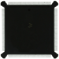
IC MCU 32BIT 16MHZ 132-PQFP
Manufacturer
Freescale Semiconductor
Series
M683xxr
Specifications of MC68332GCEH16
Core Processor
CPU32
Core Size
32-Bit
Speed
16MHz
Connectivity
EBI/EMI, SCI, SPI, UART/USART
Peripherals
POR, PWM, WDT
Number Of I /o
15
Program Memory Type
ROMless
Ram Size
2K x 8
Voltage - Supply (vcc/vdd)
4.5 V ~ 5.5 V
Oscillator Type
Internal
Operating Temperature
-40°C ~ 85°C
Package / Case
132-QFP
Cpu Family
68K/M683xx
Device Core
ColdFire
Device Core Size
32b
Frequency (max)
16MHz
Interface Type
QSPI/SCI/UART
Program Memory Size
Not Required
Total Internal Ram Size
2KB
# I/os (max)
15
Number Of Timers - General Purpose
16
Operating Supply Voltage (typ)
5V
Operating Supply Voltage (max)
5.5V
Operating Supply Voltage (min)
4.5V
Instruction Set Architecture
RISC
Operating Temp Range
-40C to 85C
Operating Temperature Classification
Industrial
Mounting
Surface Mount
Pin Count
132
Package Type
PQFP
Controller Family/series
68K
No. Of I/o's
15
Ram Memory Size
2KB
Cpu Speed
16MHz
No. Of Timers
16
Embedded Interface Type
QSPI, SCI, UART
Digital Ic Case Style
PQFP
Rohs Compliant
Yes
Processor Series
M683xx
Core
CPU32
Data Bus Width
32 bit
Data Ram Size
2 KB
Maximum Clock Frequency
16 MHz
Number Of Programmable I/os
15
Number Of Timers
16
Maximum Operating Temperature
+ 85 C
Mounting Style
SMD/SMT
Minimum Operating Temperature
- 40 C
Lead Free Status / RoHS Status
Lead free / RoHS Compliant
Eeprom Size
-
Program Memory Size
-
Data Converters
-
Lead Free Status / Rohs Status
Compliant
Available stocks
Company
Part Number
Manufacturer
Quantity
Price
Company:

Part Number:
MC68332GCEH16
Manufacturer:
Freescale Semiconductor
Quantity:
10 000


7.2.6 Parameter RAM
7.3 TPU Operation
7.3.1 Event Timing
MC68332
USER’S MANUAL
Parameter RAM occupies 256 bytes at the top of the system address map. Channel
parameters are organized as 128 16-bit words. Although all parameter word locations
in RAM can be accessed by all channels, only 100 are normally used: channels 0 to
13 use six parameter words, while channels 14 and 15 each use eight parameter
words. The parameter RAM address map in APPENDIX D REGISTER SUMMARY
shows how parameter words are organized in memory.
The host CPU specifies function parameters by writing the appropriate RAM address.
The TPU reads the RAM to determine channel operation. The TPU can also store in-
formation to be read by the CPU in RAM. Detailed descriptions of the parameters re-
quired by each time function are beyond the scope of this manual. Refer to the TPU
Reference Manual (TPURM/AD) for more information.
For pre-programmed functions, one of the parameter words associated with each
channel contains three channel control fields. These fields perform the following func-
tions:
PSC —
PAC —
TBS —
All TPU functions are related to one of the two 16-bit time bases. Functions are syn-
thesized by combining sequences of match events and capture events. Because the
primitives are implemented in hardware, the TPU can determine precisely when a
match or capture event occurs, and respond rapidly. An event register for each chan-
nel provides for simultaneity of match/capture event occurrences on all channels.
When a match or input capture event requiring service occurs, the affected channel
generates a service request to the scheduler. The scheduler determines the priority of
the request and assigns the channel to the microengine at the first available time. The
microengine performs the function defined by the content of the control store or emu-
lation RAM, using parameters from the parameter RAM.
Match and capture events are handled by independent channel hardware. This pro-
vides an event accuracy of one time-base clock period, regardless of the number of
channels that are active. An event normally causes a channel to request service. How-
ever, before an event can be serviced, any pending previous requests must be ser-
viced. The time needed to respond to and service an event is determined by the
number of channels requesting service, the relative priorities of the channels request-
ing service, and the microcode execution time of the active functions. Worst-case
Forces the output level of the pin.
For input capture, PAC specifies the edge transition to be detected. For out-
put comparison, PAC specifies the logic level to be output when a match oc-
curs.
Specifies channel direction (input or output) and assigns a time base to the
input capture and output compare functions of the channel.
Freescale Semiconductor, Inc.
For More Information On This Product,
Go to: www.freescale.com
TIME PROCESSOR UNIT
7-3
Related parts for MC68332GCEH16
Image
Part Number
Description
Manufacturer
Datasheet
Request
R

Part Number:
Description:
Manufacturer:
Freescale Semiconductor, Inc
Datasheet:
Part Number:
Description:
Manufacturer:
Freescale Semiconductor, Inc
Datasheet:
Part Number:
Description:
Manufacturer:
Freescale Semiconductor, Inc
Datasheet:
Part Number:
Description:
Manufacturer:
Freescale Semiconductor, Inc
Datasheet:
Part Number:
Description:
Manufacturer:
Freescale Semiconductor, Inc
Datasheet:
Part Number:
Description:
Manufacturer:
Freescale Semiconductor, Inc
Datasheet:
Part Number:
Description:
Manufacturer:
Freescale Semiconductor, Inc
Datasheet:
Part Number:
Description:
Manufacturer:
Freescale Semiconductor, Inc
Datasheet:
Part Number:
Description:
Manufacturer:
Freescale Semiconductor, Inc
Datasheet:
Part Number:
Description:
Manufacturer:
Freescale Semiconductor, Inc
Datasheet:
Part Number:
Description:
Manufacturer:
Freescale Semiconductor, Inc
Datasheet:
Part Number:
Description:
Manufacturer:
Freescale Semiconductor, Inc
Datasheet:
Part Number:
Description:
Manufacturer:
Freescale Semiconductor, Inc
Datasheet:
Part Number:
Description:
Manufacturer:
Freescale Semiconductor, Inc
Datasheet:
Part Number:
Description:
Manufacturer:
Freescale Semiconductor, Inc
Datasheet: