DEMO9S08LC60 Freescale Semiconductor, DEMO9S08LC60 Datasheet - Page 69
DEMO9S08LC60
Manufacturer Part Number
DEMO9S08LC60
Description
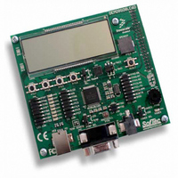
BOARD DEMO FOR 9S08LC60
Manufacturer
Freescale Semiconductor
Type
MCUr
Datasheets
1.DEMO9S08LC60.pdf
(360 pages)
2.DEMO9S08LC60.pdf
(32 pages)
3.DEMO9S08LC60.pdf
(2 pages)
Specifications of DEMO9S08LC60
Contents
Evaluation Board
Processor To Be Evaluated
MC9S08LC60
Interface Type
RS-232, USB
Silicon Manufacturer
Freescale
Core Architecture
HCS08
Core Sub-architecture
HCS08
Silicon Core Number
MC9S08
Silicon Family Name
S08LC
Rohs Compliant
Yes
For Use With/related Products
MC9S08LC60
Lead Free Status / RoHS Status
Lead free / RoHS Compliant


5.6
The MC9S08LC60 Series includes a system to protect against low voltage conditions to protect memory
contents and control MCU system states during supply voltage variations. The system comprises a
power-on reset (POR) circuit and an LVD circuit with a user selectable trip voltage, either high (V
or low (V
by LVDV in SPMSC2. The LVD is disabled upon entering any of the stop modes unless the LVDSE bit is
set. If LVDSE and LVDE are both set, then the MCU cannot enter stop1 or stop2, and the current
consumption in stop3 with the LVD enabled will be greater.
5.6.1
When power is initially applied to the MCU, or when the supply voltage drops below the V
POR circuit will cause a reset condition. As the supply voltage rises, the LVD circuit will hold the chip in
reset until the supply has risen above the V
following a POR.
5.6.2
The LVD can be configured to generate a reset upon detection of a low voltage condition by setting
LVDRE to 1. After an LVD reset has occurred, the LVD system will hold the MCU in reset until the supply
voltage has risen above the level determined by LVDV. The LVD bit in the SRS register is set following
either an LVD reset or POR.
5.6.3
When a low voltage condition is detected and the LVD circuit is configured for interrupt operation (LVDE
set, LVDIE set, and LVDRE clear), then LVDF will be set and an LVD interrupt will occur.
5.6.4
The LVD system has a low voltage warning flag to indicate to the user that the supply voltage is
approaching, but is still above, the LVD voltage. The LVW does not have an interrupt associated with it.
There are two user selectable trip voltages for the LVW, one high (V
voltage is selected by LVWV in SPMSC3.
5.7
The real-time interrupt function can be used to generate periodic interrupts. The RTI can accept two
sources of clocks, the 1-kHz internal clock or an external clock if available. The RTICLKS bit in SRTISC
is used to select the RTI clock source.
Either clock source can be used when the MCU is in run, wait or stop3 mode. When using the external
oscillator in stop3, it must be enabled in stop (EREFSTEN = 1) and configured for low frequency operation
(RANGE = 0). Only the internal 1-kHz clock source can be selected to wake the MCU from stop1 or stop2
modes.
Freescale Semiconductor
LVDL
Low-Voltage Detect (LVD) System
Real-Time Interrupt (RTI)
Power-On Reset Operation
LVD Reset Operation
LVD Interrupt Operation
Low-Voltage Warning (LVW)
). The LVD circuit is enabled when LVDE in SPMSC1 is high and the trip voltage is selected
MC9S08LC60 Series Data Sheet: Technical Data, Rev. 4
LVDL
level. Both the POR bit and the LVD bit in SRS are set
Chapter 5 Resets, Interrupts, and System Configuration
LVWH
) and one low (V
LVWL
POR
). The trip
level, the
LVDH
69
)
Related parts for DEMO9S08LC60
Image
Part Number
Description
Manufacturer
Datasheet
Request
R

Part Number:
Description:
Manufacturer:
Freescale Semiconductor, Inc
Datasheet:
Part Number:
Description:
Manufacturer:
Freescale Semiconductor, Inc
Datasheet:
Part Number:
Description:
Manufacturer:
Freescale Semiconductor, Inc
Datasheet:
Part Number:
Description:
Manufacturer:
Freescale Semiconductor, Inc
Datasheet:
Part Number:
Description:
Manufacturer:
Freescale Semiconductor, Inc
Datasheet:
Part Number:
Description:
Manufacturer:
Freescale Semiconductor, Inc
Datasheet:
Part Number:
Description:
Manufacturer:
Freescale Semiconductor, Inc
Datasheet:
Part Number:
Description:
Manufacturer:
Freescale Semiconductor, Inc
Datasheet:
Part Number:
Description:
Manufacturer:
Freescale Semiconductor, Inc
Datasheet:
Part Number:
Description:
Manufacturer:
Freescale Semiconductor, Inc
Datasheet:
Part Number:
Description:
Manufacturer:
Freescale Semiconductor, Inc
Datasheet:
Part Number:
Description:
Manufacturer:
Freescale Semiconductor, Inc
Datasheet:
Part Number:
Description:
Manufacturer:
Freescale Semiconductor, Inc
Datasheet:
Part Number:
Description:
Manufacturer:
Freescale Semiconductor, Inc
Datasheet:
Part Number:
Description:
Manufacturer:
Freescale Semiconductor, Inc
Datasheet: