DEMO9S08LC60 Freescale Semiconductor, DEMO9S08LC60 Datasheet - Page 36
DEMO9S08LC60
Manufacturer Part Number
DEMO9S08LC60
Description
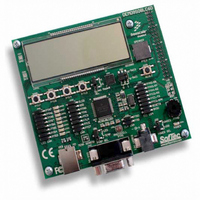
BOARD DEMO FOR 9S08LC60
Manufacturer
Freescale Semiconductor
Type
MCUr
Datasheets
1.DEMO9S08LC60.pdf
(360 pages)
2.DEMO9S08LC60.pdf
(32 pages)
3.DEMO9S08LC60.pdf
(2 pages)
Specifications of DEMO9S08LC60
Contents
Evaluation Board
Processor To Be Evaluated
MC9S08LC60
Interface Type
RS-232, USB
Silicon Manufacturer
Freescale
Core Architecture
HCS08
Core Sub-architecture
HCS08
Silicon Core Number
MC9S08
Silicon Family Name
S08LC
Rohs Compliant
Yes
For Use With/related Products
MC9S08LC60
Lead Free Status / RoHS Status
Lead free / RoHS Compliant


Chapter 3 Modes of Operation
3.6.1.1
The LVD system is capable of generating either an interrupt or a reset when the supply voltage drops below
the LVD voltage. If the LVD is enabled in stop (LVDE and LVDSE bits in SPMSC1 both set) at the time
the CPU executes a STOP instruction, then the voltage regulator remains active during stop mode.
For the ADC to operate the LVD must be left enabled when entering stop3.
3.6.1.2
Entry into the active background mode from run mode is enabled if ENBDM in BDCSCR is set. This
register is described in the
executes a STOP instruction, the system clocks to the background debug logic remain active when the
MCU enters stop mode. Because of this, background debug communication remains possible. In addition,
the voltage regulator does not enter its low-power standby state but maintains full internal regulation.
Most background commands are not available in stop mode. The memory-access-with-status commands
do not allow memory access, but they report an error indicating that the MCU is in either stop or wait
mode. The BACKGROUND command can be used to wake the MCU from stop and enter active
background mode if the ENBDM bit is set. After entering background debug mode, all background
commands are available.
3.6.2
Stop2 mode is entered by executing a STOP instruction under the conditions as shown in
of the internal circuitry of the MCU is powered off in stop2 as in stop1 with the exception of the RAM.
Upon entering stop2, all I/O pin control signals are latched so that the pins retain their states during stop2.
Exit from stop2 is performed by asserting the wake-up pins or RESET or IRQ.
In addition, the real-time interrupt (RTI) can wake the MCU from stop2 if enabled.
Upon wake-up from stop2 mode, the MCU starts up as from a power-on reset (POR):
In addition to the above, upon waking up from stop2, the PPDF bit in SPMSC2 is set. This flag is used to
direct user code to go to a stop2 recovery routine. PPDF remains set and the I/O pin states remain latched
until a 1 is written to PPDACK in SPMSC2.
To maintain I/O states for pins that were configured as general-purpose I/O before entering stop2, the user
must restore the contents of the I/O port registers, which have been saved in RAM, to the port registers
36
•
•
•
All module control and status registers are reset
The LVD reset function is enabled and the MCU remains in the reset state if V
trip point (low trip point selected due to POR)
The CPU takes the reset vector
Stop2 Mode
LVD Enabled in Stop Mode
Active BDM Enabled in Stop Mode
IRQ always functions as an active-low wakeup input when the MCU is in
stop2, regardless of how the pin is configured before entering stop2.
Development Support
MC9S08LC60 Series Data Sheet: Technical Data, Rev. 4
chapter of this data sheet. If ENBDM is set when the CPU
NOTE
Freescale Semiconductor
DD
is below the LVD
Table
3-1. Most
Related parts for DEMO9S08LC60
Image
Part Number
Description
Manufacturer
Datasheet
Request
R

Part Number:
Description:
Manufacturer:
Freescale Semiconductor, Inc
Datasheet:
Part Number:
Description:
Manufacturer:
Freescale Semiconductor, Inc
Datasheet:
Part Number:
Description:
Manufacturer:
Freescale Semiconductor, Inc
Datasheet:
Part Number:
Description:
Manufacturer:
Freescale Semiconductor, Inc
Datasheet:
Part Number:
Description:
Manufacturer:
Freescale Semiconductor, Inc
Datasheet:
Part Number:
Description:
Manufacturer:
Freescale Semiconductor, Inc
Datasheet:
Part Number:
Description:
Manufacturer:
Freescale Semiconductor, Inc
Datasheet:
Part Number:
Description:
Manufacturer:
Freescale Semiconductor, Inc
Datasheet:
Part Number:
Description:
Manufacturer:
Freescale Semiconductor, Inc
Datasheet:
Part Number:
Description:
Manufacturer:
Freescale Semiconductor, Inc
Datasheet:
Part Number:
Description:
Manufacturer:
Freescale Semiconductor, Inc
Datasheet:
Part Number:
Description:
Manufacturer:
Freescale Semiconductor, Inc
Datasheet:
Part Number:
Description:
Manufacturer:
Freescale Semiconductor, Inc
Datasheet:
Part Number:
Description:
Manufacturer:
Freescale Semiconductor, Inc
Datasheet:
Part Number:
Description:
Manufacturer:
Freescale Semiconductor, Inc
Datasheet: