DEMO9S08LC60 Freescale Semiconductor, DEMO9S08LC60 Datasheet - Page 15
DEMO9S08LC60
Manufacturer Part Number
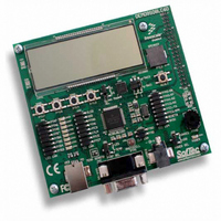
DEMO9S08LC60
Description
BOARD DEMO FOR 9S08LC60
Manufacturer
Freescale Semiconductor
Type
MCUr
Datasheets
1.DEMO9S08LC60.pdf
(360 pages)
2.DEMO9S08LC60.pdf
(32 pages)
3.DEMO9S08LC60.pdf
(2 pages)
Specifications of DEMO9S08LC60
Contents
Evaluation Board
Processor To Be Evaluated
MC9S08LC60
Interface Type
RS-232, USB
Silicon Manufacturer
Freescale
Core Architecture
HCS08
Core Sub-architecture
HCS08
Silicon Core Number
MC9S08
Silicon Family Name
S08LC
Rohs Compliant
Yes
For Use With/related Products
MC9S08LC60
Lead Free Status / RoHS Status
Lead free / RoHS Compliant


Section Number
10.6 Initialization/Application Information ..........................................................................................187
11.1 Introduction ...................................................................................................................................197
11.2 External Signal Description ..........................................................................................................201
11.3 Register Definition ........................................................................................................................201
11.4 Functional Description ..................................................................................................................207
11.5 TPM Interrupts ..............................................................................................................................211
12.1 Introduction ...................................................................................................................................213
Freescale Semiconductor
10.5.8
10.5.9
10.5.10 Clock Mode Requirements ...........................................................................................186
10.5.11 Fixed Frequency Clock .................................................................................................187
10.5.12 High Gain Oscillator .....................................................................................................187
10.6.1
10.6.2
10.6.3
10.6.4
10.6.5
11.1.1
11.1.2
11.2.1
11.2.2
11.3.1
11.3.2
11.3.3
11.3.4
11.3.5
11.4.1
11.4.2
11.4.3
11.5.1
11.5.2
11.5.3
11.5.4
12.1.1
12.1.2
FLL Lock and Loss-of-Lock Detection ........................................................................184
FLL Loss-of-Clock Detection ......................................................................................185
Introduction ..................................................................................................................187
Example #1: External Crystal = 32 kHz, Bus Frequency = 4.19 MHz ........................189
Example #2: External Crystal = 4 MHz, Bus Frequency = 20 MHz ............................191
Example #3: No External Crystal Connection, 5.4 MHz Bus Frequency ....................193
Example #4: Internal Clock Generator Trim ................................................................195
Features .........................................................................................................................199
Block Diagram ..............................................................................................................199
External TPM Clock Sources .......................................................................................201
TPMxCHn — TPMx Channel n I/O Pins .....................................................................201
Timer x Status and Control Register (TPMxSC) ..........................................................202
Timer x Counter Registers (TPMxCNTH:TPMxCNTL) .............................................203
Timer x Counter Modulo Registers (TPMxMODH:TPMxMODL) .............................204
Timer x Channel n Status and Control Register (TPMxCnSC) ....................................205
Timer x Channel Value Registers (TPMxCnVH:TPMxCnVL) ....................................206
Counter .........................................................................................................................207
Channel Mode Selection ...............................................................................................208
11.4.2.1 Input Capture Mode ......................................................................................208
11.4.2.2 Output Compare Mode .................................................................................209
11.4.2.3 Edge-Aligned PWM Mode ...........................................................................209
Center-Aligned PWM Mode ........................................................................................210
Clearing Timer Interrupt Flags .....................................................................................211
Timer Overflow Interrupt Description ..........................................................................211
Channel Event Interrupt Description ............................................................................212
PWM End-of-Duty-Cycle Events .................................................................................212
Features .........................................................................................................................216
Modes of Operation ......................................................................................................216
Serial Communications Interface (S08SCIV3)
Timer Pulse-Width Modulator (S08TPMV2)
MC9S08LC60 Series Data Sheet: Technical Data, Rev. 4
Chapter 11
Chapter 12
Title
Page
15
Related parts for DEMO9S08LC60
Image
Part Number
Description
Manufacturer
Datasheet
Request
R

Part Number:
Description:
Manufacturer:
Freescale Semiconductor, Inc
Datasheet:
Part Number:
Description:
Manufacturer:
Freescale Semiconductor, Inc
Datasheet:
Part Number:
Description:
Manufacturer:
Freescale Semiconductor, Inc
Datasheet:
Part Number:
Description:
Manufacturer:
Freescale Semiconductor, Inc
Datasheet:
Part Number:
Description:
Manufacturer:
Freescale Semiconductor, Inc
Datasheet:
Part Number:
Description:
Manufacturer:
Freescale Semiconductor, Inc
Datasheet:
Part Number:
Description:
Manufacturer:
Freescale Semiconductor, Inc
Datasheet:
Part Number:
Description:
Manufacturer:
Freescale Semiconductor, Inc
Datasheet:
Part Number:
Description:
Manufacturer:
Freescale Semiconductor, Inc
Datasheet:
Part Number:
Description:
Manufacturer:
Freescale Semiconductor, Inc
Datasheet:
Part Number:
Description:
Manufacturer:
Freescale Semiconductor, Inc
Datasheet:
Part Number:
Description:
Manufacturer:
Freescale Semiconductor, Inc
Datasheet:
Part Number:
Description:
Manufacturer:
Freescale Semiconductor, Inc
Datasheet:
Part Number:
Description:
Manufacturer:
Freescale Semiconductor, Inc
Datasheet:
Part Number:
Description:
Manufacturer:
Freescale Semiconductor, Inc
Datasheet: