DEMO9S08LC60 Freescale Semiconductor, DEMO9S08LC60 Datasheet - Page 324
DEMO9S08LC60
Manufacturer Part Number
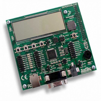
DEMO9S08LC60
Description
BOARD DEMO FOR 9S08LC60
Manufacturer
Freescale Semiconductor
Type
MCUr
Datasheets
1.DEMO9S08LC60.pdf
(360 pages)
2.DEMO9S08LC60.pdf
(32 pages)
3.DEMO9S08LC60.pdf
(2 pages)
Specifications of DEMO9S08LC60
Contents
Evaluation Board
Processor To Be Evaluated
MC9S08LC60
Interface Type
RS-232, USB
Silicon Manufacturer
Freescale
Core Architecture
HCS08
Core Sub-architecture
HCS08
Silicon Core Number
MC9S08
Silicon Family Name
S08LC
Rohs Compliant
Yes
For Use With/related Products
MC9S08LC60
Lead Free Status / RoHS Status
Lead free / RoHS Compliant


Appendix A Electrical Characteristics
A.3
This section provides information about operating temperature range, power dissipation, and package
thermal resistance. Power dissipation on I/O pins is usually small compared to the power dissipation in
on-chip logic and voltage regulator circuits and it is user-determined rather than being controlled by the
MCU design. In order to take P
actual pin voltage and V
unusually high pin current (heavy loads), the difference between pin voltage and V
small.
The average chip-junction temperature (T
where:
For most applications, P
(if P
Solving
324
1
2
3
4
Operating temperature range (packaged)
Thermal resistance
I/O
T
θ
P
P
P
Junction temperature is a function of die size, on-chip power dissipation, package thermal resistance, mounting site
(board) temperature, ambient temperature, airflow, power dissipation of other components on the board, and board
thermal resistance.
Junction to Ambient Natural Convection
1s - Single Layer Board, one signal layer
2s2p - Four Layer Board, 2 signal and 2 power layers
80-pin LQFP
64-pin LQFP
JA
D
int
I/O
A
is neglected) is:
= Ambient temperature, °C
= P
Equation A-1
= Package thermal resistance, junction-to-ambient, °C/W
= I
= Power dissipation on input and output pins — user determined
Thermal Characteristics
int
DD
+ P
× V
I/O
DD
Rating
, Watts — chip internal power
and
I/O
SS
Equation A-2
or V
<< P
MC9S08LC60 Series Data Sheet: Technical Data, Rev. 4
I/O
DD
int
into account in power calculations, determine the difference between
and can be neglected. An approximate relationship between P
and multiply by the pin current for each I/O pin. Except in cases of
Table A-2. Thermal Characteristics
P
2s2p
2s2p
T
D
J
for K gives:
1s
1s
= K ÷ (T
J
= T
) in °C can be obtained from:
A
+ (P
J
θ
JA
D
+ 273°C)
(1), (2)
× θ
Symbol
T
JA
A
,
)
(3)
,
(4)
-40 to 85
Value
64
49
66
47
SS
Freescale Semiconductor
or V
°C/W
Unit
°C
DD
will be very
D
Eqn. A-1
Eqn. A-2
and T
J
Related parts for DEMO9S08LC60
Image
Part Number
Description
Manufacturer
Datasheet
Request
R

Part Number:
Description:
Manufacturer:
Freescale Semiconductor, Inc
Datasheet:
Part Number:
Description:
Manufacturer:
Freescale Semiconductor, Inc
Datasheet:
Part Number:
Description:
Manufacturer:
Freescale Semiconductor, Inc
Datasheet:
Part Number:
Description:
Manufacturer:
Freescale Semiconductor, Inc
Datasheet:
Part Number:
Description:
Manufacturer:
Freescale Semiconductor, Inc
Datasheet:
Part Number:
Description:
Manufacturer:
Freescale Semiconductor, Inc
Datasheet:
Part Number:
Description:
Manufacturer:
Freescale Semiconductor, Inc
Datasheet:
Part Number:
Description:
Manufacturer:
Freescale Semiconductor, Inc
Datasheet:
Part Number:
Description:
Manufacturer:
Freescale Semiconductor, Inc
Datasheet:
Part Number:
Description:
Manufacturer:
Freescale Semiconductor, Inc
Datasheet:
Part Number:
Description:
Manufacturer:
Freescale Semiconductor, Inc
Datasheet:
Part Number:
Description:
Manufacturer:
Freescale Semiconductor, Inc
Datasheet:
Part Number:
Description:
Manufacturer:
Freescale Semiconductor, Inc
Datasheet:
Part Number:
Description:
Manufacturer:
Freescale Semiconductor, Inc
Datasheet:
Part Number:
Description:
Manufacturer:
Freescale Semiconductor, Inc
Datasheet: