DEMO9S08LC60 Freescale Semiconductor, DEMO9S08LC60 Datasheet - Page 129
DEMO9S08LC60
Manufacturer Part Number
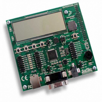
DEMO9S08LC60
Description
BOARD DEMO FOR 9S08LC60
Manufacturer
Freescale Semiconductor
Type
MCUr
Datasheets
1.DEMO9S08LC60.pdf
(360 pages)
2.DEMO9S08LC60.pdf
(32 pages)
3.DEMO9S08LC60.pdf
(2 pages)
Specifications of DEMO9S08LC60
Contents
Evaluation Board
Processor To Be Evaluated
MC9S08LC60
Interface Type
RS-232, USB
Silicon Manufacturer
Freescale
Core Architecture
HCS08
Core Sub-architecture
HCS08
Silicon Core Number
MC9S08
Silicon Family Name
S08LC
Rohs Compliant
Yes
For Use With/related Products
MC9S08LC60
Lead Free Status / RoHS Status
Lead free / RoHS Compliant


9.3.2
Read: anytime
Freescale Semiconductor
DUTY[1:0]
LCLK[2:0]
LCDSTP3
LCDWAI
LCDIEN
Reset
Field
Field
5:3
1:0
7
1
0
W
R
LCDIEN
LCD Control Register 1 (LCDCR1)
LCD Clock Prescaler — The LCD module clock prescaler bits are used as a clock divider to generate the LCD
waveform base clock as shown in
cycle configuration to determine the LCD module frame frequency.LCD module frame frequency calculations are
provided in 9.4.1.3/p.139.
LCD Duty Select — DUTY[1:0] bits select the duty cycle of the LCD module driver.
00 Reserved.
01 Use BP[1:0] (1/2 duty cycle). This mode forces the multiplexed BP3/FP40 pin to be configured as FP40
10 Use BP[2:0] (1/3 duty cycle). This mode forces the multiplexed BP3/FP40 pin to be configured as FP40
11 Use BP[3:0] (1/4 duty cycle). This mode forces the multiplexed BP3/FP40 pin to be configured as BP3
LCD Module Frame Frequency Interrupt Enable — Enables an LCD interrupt.event that coincides with the
LCD module frame frequency (LPWAVE=0) or sub-frame frequency (LPWAVE=1).
0 The start of the LCD module frame causes a LCD module interrupt request.
1 No Interrupt request is generated by this event.
LCD Module Driver and Charge Pump Stop While in Wait Mode
0 Allows the LCD driver and charge pump to continue running during wait mode.
1 Disables the LCD driver and charge pump whenever the MCU goes into wait mode.
LCD Module Driver and Charge Pump Stop While in Stop3 Mode
0 Allows the LCD module driver and charge pump to continue running during stop3.
1 Disables the LCD module driver and charge pump whenever the MCU goes into stop3.
0
7
(default)
LCD Waveform Base Clock
= Unimplemented or Reserved
0
0
6
Table 9-4. LCDCR0 Field Descriptions (continued)
MC9S08LC60 Series Data Sheet: Technical Data, Rev. 4
Figure 9-4. LCD Control Register 1 (LCDCR1)
Table 9-5. LCDCR1 Field Descriptions
0
0
5
Equation
=
9-1. The waveform base clock is used, with the LCD module duty
16 x 2
0
0
4
LCDCLK
Description
Description
LCLK[2:0]
3
0
0
Chapter 9 Liquid Crystal Display Driver (S08LCDV1)
0
0
2
where LCDCLK ≅ 32.768 kHz
LCDWAI
0
1
LCDSTP3
Eqn. 9-1
0
0
129
Related parts for DEMO9S08LC60
Image
Part Number
Description
Manufacturer
Datasheet
Request
R

Part Number:
Description:
Manufacturer:
Freescale Semiconductor, Inc
Datasheet:
Part Number:
Description:
Manufacturer:
Freescale Semiconductor, Inc
Datasheet:
Part Number:
Description:
Manufacturer:
Freescale Semiconductor, Inc
Datasheet:
Part Number:
Description:
Manufacturer:
Freescale Semiconductor, Inc
Datasheet:
Part Number:
Description:
Manufacturer:
Freescale Semiconductor, Inc
Datasheet:
Part Number:
Description:
Manufacturer:
Freescale Semiconductor, Inc
Datasheet:
Part Number:
Description:
Manufacturer:
Freescale Semiconductor, Inc
Datasheet:
Part Number:
Description:
Manufacturer:
Freescale Semiconductor, Inc
Datasheet:
Part Number:
Description:
Manufacturer:
Freescale Semiconductor, Inc
Datasheet:
Part Number:
Description:
Manufacturer:
Freescale Semiconductor, Inc
Datasheet:
Part Number:
Description:
Manufacturer:
Freescale Semiconductor, Inc
Datasheet:
Part Number:
Description:
Manufacturer:
Freescale Semiconductor, Inc
Datasheet:
Part Number:
Description:
Manufacturer:
Freescale Semiconductor, Inc
Datasheet:
Part Number:
Description:
Manufacturer:
Freescale Semiconductor, Inc
Datasheet:
Part Number:
Description:
Manufacturer:
Freescale Semiconductor, Inc
Datasheet: