DEMO9S08LC60 Freescale Semiconductor, DEMO9S08LC60 Datasheet - Page 154
DEMO9S08LC60
Manufacturer Part Number
DEMO9S08LC60
Description
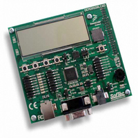
BOARD DEMO FOR 9S08LC60
Manufacturer
Freescale Semiconductor
Type
MCUr
Datasheets
1.DEMO9S08LC60.pdf
(360 pages)
2.DEMO9S08LC60.pdf
(32 pages)
3.DEMO9S08LC60.pdf
(2 pages)
Specifications of DEMO9S08LC60
Contents
Evaluation Board
Processor To Be Evaluated
MC9S08LC60
Interface Type
RS-232, USB
Silicon Manufacturer
Freescale
Core Architecture
HCS08
Core Sub-architecture
HCS08
Silicon Core Number
MC9S08
Silicon Family Name
S08LC
Rohs Compliant
Yes
For Use With/related Products
MC9S08LC60
Lead Free Status / RoHS Status
Lead free / RoHS Compliant


Chapter 9 Liquid Crystal Display Driver (S08LCDV1)
The output of the voltage divider block is V
Using the charge pump, the value of V
equal to the voltage required to energize the LCD panel, V
approximately 3-V; while for 5-V LCD glass, V
Depending on the LCDCPMS bit configuration, V
Section 9.4.4, “LCD Charge Pump, Voltage Divider, and Power Supply
selected V
In addition to V
(LCDCPEN = 1). For a typical LCD panel, the bias voltages in 1/3 bias mode would be:
9.4.4.2.2
When VSPUPPLY[1:0] = 11, powersw1, powersw2, and powersw3 are deasserted. Moreover with
powersw3 deasserted, the buffer is disabled ((~BBYPASS & pwersw3) = 0), so V
in a tri-state condition. V
requires an external power source for V
charge pump is enabled, external power must be applied to either V
9.4.4.2.3
V
VSUPPLY[1:0] = 00 or 01(see
must be enabled (LCDCPEN = 1).
VSUPPLY[1:0] bit field when using both 3-V and 5-V LCD panels.
154
DD
•
•
•
•
is specified to be from 1.8 V to 3.6 V. V
V
V
V
V
3
2
1
0
LL1
= V
= V
= V
= V
1.4 V
1.5 V
1.7 V
1.8 V
V
LCD
and V
LL3
LL2
LL1
SS
V
segment. Since V
configured so that it is 3 V or 5 V, depending on the LCD panel specification.
LCD External Power Supply, VSPUPPLY[1:0] = 11
LCD Internal Power Supply, VSUPPLY[1:0] = 00 or 01
LL1
LCDON
= V
= 2
= V
and V
LL3
LCDON
ref
×
V
is the LCD panel driving voltage required to turn on an LCD
values based on the input value of V
DD
LL3
ref
MC9S08LC60 Series Data Sheet: Technical Data, Rev. 4
is not available to power the LCD module internally, so the LCD module
(2/3) × 1.4 V
(2/3) × 1.5 V
(2/3) × 1.7 V
(2/3) × 1.8 V
V
, V
= 3
LL1
Table
LL2
LL3
= V
×
Table 9-20
V
Voltage Doubler
ref
is also generated internally when the charge pump is enabled
and V
LCDCPMS = 0
9-18). When powering the LCD module using V
ref
Table 9-19. V
LL1
LL1,
is tripled and outputted as V
LCDON
LL1.
V
DD
LL2,
V
provides recommendations regarding configuration of the
V
LL3
LL3
is used as the LCD module power supply when
LL1
NOTE
LL1
are equivalent, V
LL3
2.8 V
3.0 V
3.3 V
3.6 V
and V
= 3 × V
should be approximately 5-V.
is connected to the internal charge pump via the V
Typical Values
will be equal to 3*V
LL3
ref
LCDON.
when the charge pump is disabled. If the
LCD
.
For 3-V LCD glass, V
V
LL3
LL1,
LL1
1.67 V
1.4 V
1.5 V
1.8 V
LL3.
= V
should be
Operation).
V
LL2,
ref
Voltage Tripler
LCDCPMS = 1
LCD
V
LL3
or V
or 3*(2/3*V
, a LCD bias voltage, is
LCD
LL3
Table 9-19
V
Freescale Semiconductor
DD
LL3
will be configured
.
, the charge pump
4.2 V
4.5 V
5.0 V
5.4 V
= 3 × V
LL3
LCD
should be
ref
shows the
) (see
ref.
Related parts for DEMO9S08LC60
Image
Part Number
Description
Manufacturer
Datasheet
Request
R

Part Number:
Description:
Manufacturer:
Freescale Semiconductor, Inc
Datasheet:
Part Number:
Description:
Manufacturer:
Freescale Semiconductor, Inc
Datasheet:
Part Number:
Description:
Manufacturer:
Freescale Semiconductor, Inc
Datasheet:
Part Number:
Description:
Manufacturer:
Freescale Semiconductor, Inc
Datasheet:
Part Number:
Description:
Manufacturer:
Freescale Semiconductor, Inc
Datasheet:
Part Number:
Description:
Manufacturer:
Freescale Semiconductor, Inc
Datasheet:
Part Number:
Description:
Manufacturer:
Freescale Semiconductor, Inc
Datasheet:
Part Number:
Description:
Manufacturer:
Freescale Semiconductor, Inc
Datasheet:
Part Number:
Description:
Manufacturer:
Freescale Semiconductor, Inc
Datasheet:
Part Number:
Description:
Manufacturer:
Freescale Semiconductor, Inc
Datasheet:
Part Number:
Description:
Manufacturer:
Freescale Semiconductor, Inc
Datasheet:
Part Number:
Description:
Manufacturer:
Freescale Semiconductor, Inc
Datasheet:
Part Number:
Description:
Manufacturer:
Freescale Semiconductor, Inc
Datasheet:
Part Number:
Description:
Manufacturer:
Freescale Semiconductor, Inc
Datasheet:
Part Number:
Description:
Manufacturer:
Freescale Semiconductor, Inc
Datasheet: