DEMO9S08LC60 Freescale Semiconductor, DEMO9S08LC60 Datasheet
DEMO9S08LC60
Specifications of DEMO9S08LC60


Related parts for DEMO9S08LC60

DEMO9S08LC60 Summary of contents
Page 1
... DEMO9S08LC60 Demonstration Board for Freescale MC9S08LC60 User’s Manual ...
Page 2
...
Page 3
... DEMO9S08LC60 Demonstration Board for Freescale MC9S08LC60 (80-Pin LQFP) User’s Manual Revision 1.0 Copyright © 2006 SofTec Microsystems DC01175 ® ...
Page 4
... THEREOF. Trademarks SofTec Microsystems is a registered trademark of SofTec Microsystems, Spa. Freescale™ and the Freescale logo are trademarks of Freescale Semiconductor, Inc. Microsoft and Windows are trademarks or registered trademarks of Microsoft Corporation registered trademark of International Business Machines Corporation. Other products and company names listed are trademarks or trade names of their respective companies. ...
Page 5
... Standalone Mode 15 5.3 Host Mode 15 6 Application Tutorial 17 6.1 Overview 17 6.2 Step-by-Step Tutorial 17 7 Summary of Jumper and Connector Settings 21 7.1 Jumpers 21 7.2 Connectors 23 8 Troubleshooting 25 8.1 USB Driver Problems 25 8.2 Communication Problems between the PC and the Demo Board 25 DEMO9S08LC60 User's Manual Page 3 ...
Page 6
...
Page 7
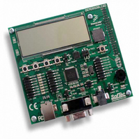
... The DEMO9S08LC60 Demonstration board has been designed for the evaluation, demonstration and the debugging of the Freescale MC9S08LC60 microcontroller. The DEMO9S08LC60 can be used as a standalone application, or via its built-in USB-to-BDM bridge, or together the Freescale Student Learning Kit (Freescale code: MCUSLK) through an external 40-pin I/O header female connector. ...
Page 8
Introduction Note: the MC9S08LC60 datasheet is available for download at i www.freescale.com. Page 6 ...
Page 9
... Hardware Features 2.1 Demonstration Board Features The DEMO9S08LC60 board features: A MC9S08LC60 microcontroller (in 80-pin LQFP package, already programmed with a demo application); One clock sources: a 32.768 KHz crystal, selectable via the “CLK ENA” jumpers Power Supply Input Connector; Power input selection jumpers for selecting the input voltage source input connector ...
Page 10
... A piezoelectric speaker, together with a jumper to connect/disconnect it to/from o the PTC2 pin of the microcontroller; A custom LCD RS-232 channel connected to the microcontroller’s SCI serial communication interface. The microcontroller’s PTC0/RxD and PTC1/TxD lines are used by the RS-232 channel. Page 8 The DEMO9S08LC60 Demonstration Board ...
Page 11
... A USB port; CD-ROM drive for installation. 3.3 Installing CodeWarrior Development Studio To install the CodeWarrior Development Studio Special Edition, insert the CodeWarrior CD- ROM into your computer’s CD-ROM drive. A startup window will automatically appear. Follow the on-screen instructions. DEMO9S08LC60 User's Manual Page 9 ...
Page 12
Software Setup 3.4 Installing SofTec Microsystems Additional Components The SofTec Microsystems Additional Components install all of the other required components to your hard drive. These components include: The Demonstration Board’s USB driver; The software plug-in for CodeWarrior; Examples; Demonstration Board’s ...
Page 13
... New Hardware Wizard” procedure, asking you to specify the driver to use for the instrument. On Windows XP (SP2) the following dialog box will appear. Select the “No, not this time” option and click the “Next >” button. 6. The following dialog box will appear. DEMO9S08LC60 User's Manual Page 11 ...
Page 14
Hardware Setup Click the “Next >” button. 7. Depending on your Windows settings, the following warning may appear. Note: this warning is related to the fact that the USB driver used by i the Demonstration Board is not digitally signed ...
Page 15
... I/O header connector. The “POWER SEL” jumper allows you to power the board through either the input connector or the USB connector. When using the I/O header connector, its pin 1 is always connected to the 3 line of the carrier board. DEMO9S08LC60 User's Manual Page 13 ...
Page 16
...
Page 17
... In host mode the program execution is controlled by the host PC through the “USB” connector. You can use the PC to debug the application by, for example, executing the program step by step and watching how the microcontroller registers vary, using the provided CodeWarrior Development Studio. DEMO9S08LC60 User's Manual Page 15 ...
Page 18
Operating Modes Note: all MCUs in the S08 family contain a single-wire background debug i interface which supports in-circuit programming of on-chip non-volatile memory. This system does not interfere with normal application resources. It does not use any user memory ...
Page 19
... Open” and choose the “\Program Files\Freescale\CodeWarrior for HC08 V5.1\(CodeWarrior Examples)\HCS08\Evaluation Board Examples\DEMO9S08LC60\C\Demo\Demo.mcp”. 5. Click “Open”. The Project Window will open. 6. The C code of this example is contained in the “main.c” file. Double click open it. DEMO9S08LC60 User's Manual Page 17 ...
Page 20
Application Tutorial 7. From the main menu, choose “Project > Debug”. This will compile the source code, generate an executable file and download it to the demo board. A new debugger environment will open. Page 18 ...
Page 21
... HC08 V5.1\(CodeWarrior Examples)\HCS08\Evaluation Board Examples\DEMO9S08LC60\C\” directory: Accelerometer: variation of acceleration along one of the three axis varies the output on the LCD and emits a sound on the speaker. SCI: prints on the LCD a line of text sent by the PC through an RS-232 terminal application. DEMO9S08LC60 User's Manual Page 19 ...
Page 22
Application Tutorial You can continue to experiment with the CodeWarrior user interface and discover by yourself its potentialities. For an in-depth guide of all of the user interface features, select “Help > CodeWarrior Help” from CodeWarrior Development Studio’s main menu. ...
Page 23
... Not Installed: POWER SELECTION 1-2 (“UNREG”): 2-3 (“USB”): PTA7 SELECTION 1-2: 2-3: DEMO9S08LC60 User's Manual The indicated microcontroller line is connected to the indicated user I/O function (default) The indicated microcontroller line is not connected to the indicated user I/O function The crystal oscillator is connected to ...
Page 24
Summary of Jumper and Connector Settings Name Reference J302 g-Sel2 g-Sel1 0 1 J303 J304 1 J401 1 Page 22 Description/Pinout G SELECTION Selects the accelerometer sensitivity according to the following table. g-Sel2 g-Sel1 ...
Page 25
... Connectors Name Reference J101 DEMO9S08LC60 User's Manual Description/Pinout 40-Pin I/O Header Female Connector 1. VDD (3 PTC7 3. GND 4. RST# 5. PTC1 6. BKGD 7. PTC0 8. N.C. 9. PTC4 10. PTA0 11. PTC5 12. PTA1 13. PTC2 14. PTA2 15. PTC3 16. PTA3 17. PTB5 18. PTA4 19. PTB4 20. PTA5 21. PTB6 22. PTA6 23. PTB7 24. PTA7 25. N.C. 26. N.C. 27. ...
Page 26
Summary of Jumper and Connector Settings Name Reference J104 J201 2 1 J203 J501 Page 24 Description/Pinout BDM Connector (Not Populated) 1. BKGD 2. GND 3. N.C. 4. RESET/VPP 5. ...
Page 27
... Make sure that the “VDD ENA” jumper in the “IO1 ENA” jumper strip is installed. 3. Make sure that the “POWER SEL” jumper selects the appropriate power source (typically “USB” when the board is connected to the PC). DEMO9S08LC60 User's Manual Page 25 ...
Page 28
...
Page 29
...
Page 30
...
Page 31
...
Page 32
...