Z16F2800100ZCOG Zilog, Z16F2800100ZCOG Datasheet - Page 133
Z16F2800100ZCOG
Manufacturer Part Number
Z16F2800100ZCOG
Description
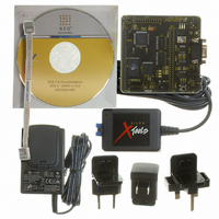
DEV KIT FOR Z16F ZNEO
Manufacturer
Zilog
Series
ZNEO™r
Type
MCUr
Datasheets
1.Z16F2800100ZCOG.pdf
(2 pages)
2.Z16F2800100ZCOG.pdf
(30 pages)
3.Z16F2800100ZCOG.pdf
(388 pages)
Specifications of Z16F2800100ZCOG
Contents
Evaluation Board, Software and Documentation
For Use With/related Products
Z16F Series
For Use With
269-4661 - KIT ACC ETHERNET SMART CABLE
Lead Free Status / RoHS Status
Lead free / RoHS Compliant
Other names
269-4537


PS022008-0810
PWM Duty Cycle Registers
Independent and Complementary PWM Outputs
Center-Aligned PWM Mode Period
EDGE-ALIGNED Mode
In EDGE-ALINGED PWM mode, a 12-bit up counter creates the PWM period with a
minimum resolution equal to the PWM clock source period. The counter counts up to the
Reload value, resets to
CENTER-ALINGED Mode
In CENTER-ALINGED PWM mode, a 12-bit up/down counter creates the PWM period
with a minimum resolution equal to twice the PWM clock source period. The counter
counts up to the Reload value and then counts down to 0.
The PWM duty cycle registers (PWMH0D, PWML0D, PWMH1D, PWML1D,
PWMH2D, PWML2D) contain a 16-bit signed value where bit 15 is the sign bit. The duty
cycle value is compared to the current 12-bit unsigned PWM count value. If the PWM
duty cycle value is set less than or equal to 0, the PWM output is deasserted for full PWM
period. If the PWM duty cycle value is set to a value greater than the PWM Reload value,
the PWM output is asserted for full PWM period.
The six PWM outputs are configured to operate independently or as three complementary
pairs. Operation as six independent PWM channels are enabled by setting the INDEN bit
in the
output uses its own PWM duty cycle value.
When PWM outputs are configured to operate as three complementary pairs, the PWM
duty cycle values PWMH0D, PWMH1D, and PWMH2D control the modulator output. In
COMPLEMENTARY OUTPUT mode deadband time is also inserted.
The POLx bits in the
the high- and low-side signals. As illustrated in
when the POLx bits are cleared to 0, the PWM high-side output will start in the on-state
Edge-Aligned PWM Mode Period
PWM Control 1 Register
PWM Control 1 Register (PWMCTL1)
000H
P R E L I M I N A R Y
, and then resumes counting.
(PWMCTL1). In INDEPENDENT mode, each PWM
=
=
2 Prescaler
--------------------------------------------------------------------- -
Prescaler Reload Value
------------------------------------------------------------ -
Figure 21
f
PWMclk
f
PWMclk
and
Reload Value
select the relative polarity of
Figure 22
Multi-Channel PWM Timer
Product Specification
ZNEO
on page 117,
Z16F Series
118
Related parts for Z16F2800100ZCOG
Image
Part Number
Description
Manufacturer
Datasheet
Request
R

Part Number:
Description:
Communication Controllers, ZILOG INTELLIGENT PERIPHERAL CONTROLLER (ZIP)
Manufacturer:
Zilog, Inc.
Datasheet:

Part Number:
Description:
KIT DEV FOR Z8 ENCORE 16K TO 64K
Manufacturer:
Zilog
Datasheet:

Part Number:
Description:
KIT DEV Z8 ENCORE XP 28-PIN
Manufacturer:
Zilog
Datasheet:

Part Number:
Description:
DEV KIT FOR Z8 ENCORE 8K/4K
Manufacturer:
Zilog
Datasheet:

Part Number:
Description:
KIT DEV Z8 ENCORE XP 28-PIN
Manufacturer:
Zilog
Datasheet:

Part Number:
Description:
DEV KIT FOR Z8 ENCORE 4K TO 8K
Manufacturer:
Zilog
Datasheet:
Part Number:
Description:
CMOS Z8 microcontroller. ROM 16 Kbytes, RAM 256 bytes, speed 16 MHz, 32 lines I/O, 3.0V to 5.5V
Manufacturer:
Zilog, Inc.
Datasheet:
Part Number:
Description:
Low-cost microcontroller. 512 bytes ROM, 61 bytes RAM, 8 MHz
Manufacturer:
Zilog, Inc.
Datasheet:
Part Number:
Description:
Z8 4K OTP Microcontroller
Manufacturer:
Zilog, Inc.
Datasheet:
Part Number:
Description:
CMOS SUPER8 ROMLESS MCU
Manufacturer:
Zilog, Inc.
Datasheet:
Part Number:
Description:
SL1866 CMOSZ8 OTP Microcontroller
Manufacturer:
Zilog, Inc.
Datasheet:
Part Number:
Description:
SL1866 CMOSZ8 OTP Microcontroller
Manufacturer:
Zilog, Inc.
Datasheet:
Part Number:
Description:
OTP (KB) = 1, RAM = 125, Speed = 12, I/O = 14, 8-bit Timers = 2, Comm Interfaces Other Features = Por, LV Protect, Voltage = 4.5-5.5V
Manufacturer:
Zilog, Inc.
Datasheet:
Part Number:
Description:
Manufacturer:
Zilog, Inc.
Datasheet: