PNX1501E,557 NXP Semiconductors, PNX1501E,557 Datasheet - Page 809
PNX1501E,557
Manufacturer Part Number
PNX1501E,557
Description
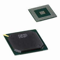
IC MEDIA PROC 266MHZ 456-BGA
Manufacturer
NXP Semiconductors
Datasheet
1.PNX1502EG557.pdf
(828 pages)
Specifications of PNX1501E,557
Applications
Multimedia
Core Processor
TriMedia
Controller Series
Nexperia
Interface
I²C, 2-Wire Serial
Number Of I /o
61
Voltage - Supply
1.14 V ~ 1.26 V
Operating Temperature
0°C ~ 85°C
Mounting Type
Surface Mount
Package / Case
456-BGA
Lead Free Status / RoHS Status
Lead free / RoHS Compliant
Program Memory Type
-
Ram Size
-
Other names
935274728557
PNX1501E
PNX1501E
PNX1501E
PNX1501E
Available stocks
Company
Part Number
Manufacturer
Quantity
Price
Company:

Part Number:
PNX1501E,557
Manufacturer:
NXP Semiconductors
Quantity:
10 000


Philips Semiconductors
Volume 1 of 1
5. Example: Audio In—Programmer’s View
Table 4: Precise Mapping Audio In Sample Time and Bits to Memory Bytes
PNX15XX_SER_3
Product data sheet
Operating Mode
8-bit mono—little-endian or big-endian
8-bit stereo—little-endian or big-endian
16-bit mono—little-endian
16-bit mono—big-endian
16-bit stereo—little-endian
16-bit stereo—big-endian
Figure 5:
8-bit
mono
8-bit
stereo
16-bit
mono
16-bit
stereo
Audio In Memory Data Structure (Programmer’s View)
addr
left
addr
left
n
n
addr
left
addr
left
The PNX15xx Series Audio In module receives mono or stereo, 8 or 16-bit/sample
audio data and fills memory with an 8 or 16-bit data structure. The data structure is
put in memory according to both endian mode laws.
A programmer’s view of the Audio In function is sketched in
programmer sees the address of each item (according to the DMA rule), and expects
that 16-bit values are correctly stored in memory according to the CPU law. The DMA
logic of the Audio In module therefore needs to write data in memory (byte) locations
precisely, per
registers of the Audio In module per
the same bit-layout in the CPU register, regardless of endian mode.
n
n
addr+1
left
addr+1
right
n+1
n
Table
addr+2
left
addr+2
left
n+2
n+1
Rev. 3 — 17 March 2006
addr+2
left
addr+2
right
4. Note the programmer also sees the Control and Status
m[addr]
left
left
left
left
left
left
n+1
n
n
n
n
n
n
n
addr+3
left
addr+3
right
[7:0]
[7:0]
[7:0]
[15:8]
[7:0]
[15:8]
n+3
n+1
addr+4
left
addr+4
left
Figure
n+4
n+2
m[addr+1]
left
right
left
left
left
left
addr+4
left
addr+4
left
n+1
n
n
n
n
[15:8]
[7:0]
[15:8]
[7:0]
n
n+2
n+1
[7:0]
[7:0]
6. These registers are always seen with
addr+5
left
addr+5
right
n+5
n+2
m[addr+2]
left
left
left
left
right
right
© Koninklijke Philips Electronics N.V. 2006. All rights reserved.
addr+6
left
addr+6
left
n+2
n+1
n+1
n+1
n+6
n+3
n
n
PNX15xx Series
Chapter 29: Endian Mode
[7:0]
[15:8]
[7:0]
[7:0]
[7:0]
[15:8]
Figure
addr+6
left
addr+6
right
n+3
n+1
addr+7
left
addr+7
right
5. The
n+7
n+3
m[addr+3]
left
right
left
left
right
right
n+3
n+1
n+1
n+1
n
n
[15:8]
[7:0]
[7:0]
[15:8]
[7:0]
[7:0]
29-9
Related parts for PNX1501E,557
Image
Part Number
Description
Manufacturer
Datasheet
Request
R

Part Number:
Description:
Manufacturer:
NXP Semiconductors
Datasheet:
Part Number:
Description:
Digital Signal Processors & Controllers (DSP, DSC) MEDIA PROCESSOR PNX15XX/266MHZ
Manufacturer:
NXP Semiconductors
Datasheet:

Part Number:
Description:
IC MEDIA PROC 266MHZ 456-BGA
Manufacturer:
NXP Semiconductors
Datasheet:
Part Number:
Description:
NXP Semiconductors designed the LPC2420/2460 microcontroller around a 16-bit/32-bitARM7TDMI-S CPU core with real-time debug interfaces that include both JTAG andembedded trace
Manufacturer:
NXP Semiconductors
Datasheet:

Part Number:
Description:
NXP Semiconductors designed the LPC2458 microcontroller around a 16-bit/32-bitARM7TDMI-S CPU core with real-time debug interfaces that include both JTAG andembedded trace
Manufacturer:
NXP Semiconductors
Datasheet:
Part Number:
Description:
NXP Semiconductors designed the LPC2468 microcontroller around a 16-bit/32-bitARM7TDMI-S CPU core with real-time debug interfaces that include both JTAG andembedded trace
Manufacturer:
NXP Semiconductors
Datasheet:
Part Number:
Description:
NXP Semiconductors designed the LPC2470 microcontroller, powered by theARM7TDMI-S core, to be a highly integrated microcontroller for a wide range ofapplications that require advanced communications and high quality graphic displays
Manufacturer:
NXP Semiconductors
Datasheet:
Part Number:
Description:
NXP Semiconductors designed the LPC2478 microcontroller, powered by theARM7TDMI-S core, to be a highly integrated microcontroller for a wide range ofapplications that require advanced communications and high quality graphic displays
Manufacturer:
NXP Semiconductors
Datasheet:
Part Number:
Description:
The Philips Semiconductors XA (eXtended Architecture) family of 16-bit single-chip microcontrollers is powerful enough to easily handle the requirements of high performance embedded applications, yet inexpensive enough to compete in the market for hi
Manufacturer:
NXP Semiconductors
Datasheet:
Part Number:
Description:
The XA-S3 device is a member of Philips Semiconductors? XA(eXtended Architecture) family of high performance 16-bitsingle-chip microcontrollers
Manufacturer:
NXP Semiconductors
Datasheet:

Part Number:
Description:
The NXP BlueStreak LH75401/LH75411 family consists of two low-cost 16/32-bit System-on-Chip (SoC) devices
Manufacturer:
NXP Semiconductors
Datasheet:
Part Number:
Description:
The NXP LPC3130/3131 combine an 180 MHz ARM926EJ-S CPU core, high-speed USB2
Manufacturer:
NXP Semiconductors
Datasheet:
Part Number:
Description:
The NXP LPC3141 combine a 270 MHz ARM926EJ-S CPU core, High-speed USB 2
Manufacturer:
NXP Semiconductors
Part Number:
Description:
The NXP LPC3143 combine a 270 MHz ARM926EJ-S CPU core, High-speed USB 2
Manufacturer:
NXP Semiconductors