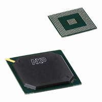
PNX1501E,557 NXP Semiconductors, PNX1501E,557 Datasheet - Page 438

PNX1501E,557
Manufacturer Part Number
PNX1501E,557
Description
IC MEDIA PROC 266MHZ 456-BGA
Manufacturer
NXP Semiconductors
Datasheet
1.PNX1502EG557.pdf
(828 pages)
Specifications of PNX1501E,557
Applications
Multimedia
Core Processor
TriMedia
Controller Series
Nexperia
Interface
I²C, 2-Wire Serial
Number Of I /o
61
Voltage - Supply
1.14 V ~ 1.26 V
Operating Temperature
0°C ~ 85°C
Mounting Type
Surface Mount
Package / Case
456-BGA
Lead Free Status / RoHS Status
Lead free / RoHS Compliant
Program Memory Type
-
Ram Size
-
Other names
935274728557
PNX1501E
PNX1501E
PNX1501E
PNX1501E
Available stocks
Company
Part Number
Manufacturer
Quantity
Price
Company:
Part Number:
PNX1501E,557
Manufacturer:
NXP Semiconductors
Quantity:
10 000
- Current page: 438 of 828
- Download datasheet (8Mb)
Philips Semiconductors
Volume 1 of 1
PNX15XX_SER_3
Product data sheet
The Dither units can be used when the bit precision of samples needs to be limited,
while preventing quantization effects in areas with almost uniform levels of shades in
a picture.
The following discussion refers to a single Dither unit, either Pre- or Post-Dither
The dither unit processes up to 10 bit inputs. It receives all the three components, Y,
U and V, on two 10 bit input buses, and dithers/rounds them down to 8 or 9 bits.
Dithering can be enabled separately for luma (Y) and chroma (U and V) components.
If the dither unit is enabled but dithering is disabled, rounding, instead of dithering, is
performed.
Whenever dithering is enabled, the dithering process alternates its activity between
adjacent pixels: either every pixel or every two pixels. Furthermore, any combination
of three alternation patterns can be selected: line, field, and frame alternations.
The Dither units are controlled by QVI_PRE_DITHER_CTRL and
QVI_POST_DITHER_CTRL MMIO registers, for the pre- and post-dither units,
respectively. Immediately after the unit is enabled, it waits for the beginning of the
following captured image before it actually starts to operate.
Enabling the dither unit resets its internal state.
Dither Mechanism
The operation mode is programmable via MODE in the dither-unit control register.
The three available modes are:
Remark: 8-bit input samples are not changed when passed through the Dither unit
(the 8 output MSBs are identical to the 8 input MSBs, but the 2 output LSBs are
changed by the dither unit).
The Dither unit independently dithers all the three components Y, U, and V in the
same way. Each input pixel is processed independently in the sense that the value of
the other inputs do not affect the processing of the current input.
The unit is enabled with DITHER_ENABLE. The programmer can select which
components are dithered; with DITHER_Y for the luma components, and
DITHER_UV, independent of Y, for the chroma components. When the dither unit is
enabled, a component that is not selected for dithering goes through rounding. The
final value of all components is saturated at 1023, which is the largest value
represented by the 10 bit output.
Whenever the dithering operation is enabled, the process of dithering alternates
between successive pixel-components, either every pixel or every two pixels, in the
same image line. This option is programmable with DOUBLE_PIXEL_ALT for Single
or Double pixel alternation.
There are another three dithering options that can be enabled or disabled
independently: alternate processing between successive lines, fields and frames.
•
•
•
10-bit input down to 8 bits of output
10-bit input down to 9 bits of output
9 bit input down to 8 bits of output.
Rev. 3 — 17 March 2006
Chapter 12: Video Input Processor
© Koninklijke Philips Electronics N.V. 2006. All rights reserved.
PNX15xx Series
12-11
Related parts for PNX1501E,557
Image
Part Number
Description
Manufacturer
Datasheet
Request
R
Part Number:
Description:
Manufacturer:
NXP Semiconductors
Datasheet:
Part Number:
Description:
Digital Signal Processors & Controllers (DSP, DSC) MEDIA PROCESSOR PNX15XX/266MHZ
Manufacturer:
NXP Semiconductors
Datasheet:

Part Number:
Description:
IC MEDIA PROC 266MHZ 456-BGA
Manufacturer:
NXP Semiconductors
Datasheet:
Part Number:
Description:
NXP Semiconductors designed the LPC2420/2460 microcontroller around a 16-bit/32-bitARM7TDMI-S CPU core with real-time debug interfaces that include both JTAG andembedded trace
Manufacturer:
NXP Semiconductors
Datasheet:

Part Number:
Description:
NXP Semiconductors designed the LPC2458 microcontroller around a 16-bit/32-bitARM7TDMI-S CPU core with real-time debug interfaces that include both JTAG andembedded trace
Manufacturer:
NXP Semiconductors
Datasheet:
Part Number:
Description:
NXP Semiconductors designed the LPC2468 microcontroller around a 16-bit/32-bitARM7TDMI-S CPU core with real-time debug interfaces that include both JTAG andembedded trace
Manufacturer:
NXP Semiconductors
Datasheet:
Part Number:
Description:
NXP Semiconductors designed the LPC2470 microcontroller, powered by theARM7TDMI-S core, to be a highly integrated microcontroller for a wide range ofapplications that require advanced communications and high quality graphic displays
Manufacturer:
NXP Semiconductors
Datasheet:
Part Number:
Description:
NXP Semiconductors designed the LPC2478 microcontroller, powered by theARM7TDMI-S core, to be a highly integrated microcontroller for a wide range ofapplications that require advanced communications and high quality graphic displays
Manufacturer:
NXP Semiconductors
Datasheet:
Part Number:
Description:
The Philips Semiconductors XA (eXtended Architecture) family of 16-bit single-chip microcontrollers is powerful enough to easily handle the requirements of high performance embedded applications, yet inexpensive enough to compete in the market for hi
Manufacturer:
NXP Semiconductors
Datasheet:
Part Number:
Description:
The XA-S3 device is a member of Philips Semiconductors? XA(eXtended Architecture) family of high performance 16-bitsingle-chip microcontrollers
Manufacturer:
NXP Semiconductors
Datasheet:

Part Number:
Description:
The NXP BlueStreak LH75401/LH75411 family consists of two low-cost 16/32-bit System-on-Chip (SoC) devices
Manufacturer:
NXP Semiconductors
Datasheet:

Part Number:
Description:
The NXP LPC3130/3131 combine an 180 MHz ARM926EJ-S CPU core, high-speed USB2
Manufacturer:
NXP Semiconductors
Datasheet:

Part Number:
Description:
The NXP LPC3141 combine a 270 MHz ARM926EJ-S CPU core, High-speed USB 2
Manufacturer:
NXP Semiconductors

Part Number:
Description:
The NXP LPC3143 combine a 270 MHz ARM926EJ-S CPU core, High-speed USB 2
Manufacturer:
NXP Semiconductors


