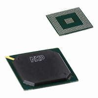
PNX1501E,557 NXP Semiconductors, PNX1501E,557 Datasheet - Page 217

PNX1501E,557
Manufacturer Part Number
PNX1501E,557
Description
IC MEDIA PROC 266MHZ 456-BGA
Manufacturer
NXP Semiconductors
Datasheet
1.PNX1502EG557.pdf
(828 pages)
Specifications of PNX1501E,557
Applications
Multimedia
Core Processor
TriMedia
Controller Series
Nexperia
Interface
I²C, 2-Wire Serial
Number Of I /o
61
Voltage - Supply
1.14 V ~ 1.26 V
Operating Temperature
0°C ~ 85°C
Mounting Type
Surface Mount
Package / Case
456-BGA
Lead Free Status / RoHS Status
Lead free / RoHS Compliant
Program Memory Type
-
Ram Size
-
Other names
935274728557
PNX1501E
PNX1501E
PNX1501E
PNX1501E
Available stocks
Company
Part Number
Manufacturer
Quantity
Price
Company:
Part Number:
PNX1501E,557
Manufacturer:
NXP Semiconductors
Quantity:
10 000
- Current page: 217 of 828
- Download datasheet (8Mb)
Philips Semiconductors
Volume 1 of 1
4. The Boot From an I
Table 10: Examples of I
PNX15XX_SER_3
Product data sheet
Size
256 bytes
512 bytes
1 kilobytes
2 kilobytes
2 kilobytes
Device
ATMEL 24C02
ATMEL 24C04
ATMEL 24C08
PHILIPS PCF85116-3 Full Array
SUMMIT SMS8198
4.1 External I
2
C EEPROM Devices
If none of the built-in scripts is suitable e.g., due to a different type of NAND-Flash or
a different memory organization or anything not matching the internal boot scripts, an
external serial boot EEPROM is required. Depending on the application
characteristics, this can be a small (1 Kilobyte or less) EEPROM that contains a small
boot script and starts the PNX15xx Series system in host-assisted mode or boot from
Flash memory or ROM devices. Alternately, a large serial EEPROM can be used to
contain a complete disk file system or an upload capability from another device than
Flash/ROM.
For a 2-Kilobyte or smaller EEPROM, the script must start at byte address 1 (not 0).
For a 4-Kilobyte or larger EEPROM, the boot script must start at byte address 0. More
details in
word value (the byte read first ends up as the least significant byte, LBS). The 32-bit
words are then interpreted as commands, as documented earlier in
Remark: It has been seen that depending on the Write Protect pin status, some
EEPROMs do not behave the same way on a write of 0 bytes
internal counter gets or does not get incremented which makes this rule of where the
first byte is located at address 0 or 1 different. Refer to EEPROM datasheet or try both
options.
The PNX15xx Series Boot module supports all I
wire EEPROMs) that use a 1-byte or 2-byte address protocol and respond to an I
device code 1010 (binary). Subtle differences exist between devices For example:
Table 10
operation for all these devices been verified.
•
•
•
•
It is recommended to avoid devices that have partial array write protection, since
such devices could be overwritten by accidental or intentional I
boot failure during the next reset.
Some devices may have additional functionality that is useful, like a watchdog
timer or a power voltage drop sensor.
Availability from different vendors may vary.
Programming protocols may vary.
2
Write Protection
Coverage
Full Array
Full Array
Full Array
Full Array
C EEPROM
lists a variety of devices. This list is by no means exhaustive, nor has
Section
2
C Boot EEPROM Types
4.3. Each set of four successive bytes is assembled into a 32-bit
Rev. 3 — 17 March 2006
Address Protocol
1 byte
1 byte
1 byte
1 byte
1 byte
2
C EEPROMs (sometimes called 2-
Comment
Tested
Includes power-on reset for board
system reset generation
© Koninklijke Philips Electronics N.V. 2006. All rights reserved.
PNX15xx Series
Chapter 6: Boot Module
(Section
2
C writes, causing
Section
4.3). The
2.3.
2
6-14
C
Related parts for PNX1501E,557
Image
Part Number
Description
Manufacturer
Datasheet
Request
R
Part Number:
Description:
Manufacturer:
NXP Semiconductors
Datasheet:
Part Number:
Description:
Digital Signal Processors & Controllers (DSP, DSC) MEDIA PROCESSOR PNX15XX/266MHZ
Manufacturer:
NXP Semiconductors
Datasheet:

Part Number:
Description:
IC MEDIA PROC 266MHZ 456-BGA
Manufacturer:
NXP Semiconductors
Datasheet:
Part Number:
Description:
NXP Semiconductors designed the LPC2420/2460 microcontroller around a 16-bit/32-bitARM7TDMI-S CPU core with real-time debug interfaces that include both JTAG andembedded trace
Manufacturer:
NXP Semiconductors
Datasheet:

Part Number:
Description:
NXP Semiconductors designed the LPC2458 microcontroller around a 16-bit/32-bitARM7TDMI-S CPU core with real-time debug interfaces that include both JTAG andembedded trace
Manufacturer:
NXP Semiconductors
Datasheet:
Part Number:
Description:
NXP Semiconductors designed the LPC2468 microcontroller around a 16-bit/32-bitARM7TDMI-S CPU core with real-time debug interfaces that include both JTAG andembedded trace
Manufacturer:
NXP Semiconductors
Datasheet:
Part Number:
Description:
NXP Semiconductors designed the LPC2470 microcontroller, powered by theARM7TDMI-S core, to be a highly integrated microcontroller for a wide range ofapplications that require advanced communications and high quality graphic displays
Manufacturer:
NXP Semiconductors
Datasheet:
Part Number:
Description:
NXP Semiconductors designed the LPC2478 microcontroller, powered by theARM7TDMI-S core, to be a highly integrated microcontroller for a wide range ofapplications that require advanced communications and high quality graphic displays
Manufacturer:
NXP Semiconductors
Datasheet:
Part Number:
Description:
The Philips Semiconductors XA (eXtended Architecture) family of 16-bit single-chip microcontrollers is powerful enough to easily handle the requirements of high performance embedded applications, yet inexpensive enough to compete in the market for hi
Manufacturer:
NXP Semiconductors
Datasheet:
Part Number:
Description:
The XA-S3 device is a member of Philips Semiconductors? XA(eXtended Architecture) family of high performance 16-bitsingle-chip microcontrollers
Manufacturer:
NXP Semiconductors
Datasheet:

Part Number:
Description:
The NXP BlueStreak LH75401/LH75411 family consists of two low-cost 16/32-bit System-on-Chip (SoC) devices
Manufacturer:
NXP Semiconductors
Datasheet:

Part Number:
Description:
The NXP LPC3130/3131 combine an 180 MHz ARM926EJ-S CPU core, high-speed USB2
Manufacturer:
NXP Semiconductors
Datasheet:

Part Number:
Description:
The NXP LPC3141 combine a 270 MHz ARM926EJ-S CPU core, High-speed USB 2
Manufacturer:
NXP Semiconductors

Part Number:
Description:
The NXP LPC3143 combine a 270 MHz ARM926EJ-S CPU core, High-speed USB 2
Manufacturer:
NXP Semiconductors


